Mitsubishi Outlander (2003+). Manual - part 384
 

  Index      Mitsubishi     Mitsubishi Outlander - service repair manual 2003 year


Search            


Content   ..  382  383  384  385   ..


Mitsubishi Outlander (2003+). Manual - part 384


TROUBLESHOOTING

SUPPLEMENTAL RESTRAINT SYSTEM (SRS)

52B-135

PROBABLE CAUSES

Damaged wiring harnesses or connectors

Short to earth in the side air bag module (RH) 
(squib) harness

Malfunction of the SRS-ECU

DIAGNOSIS PROCEDURE

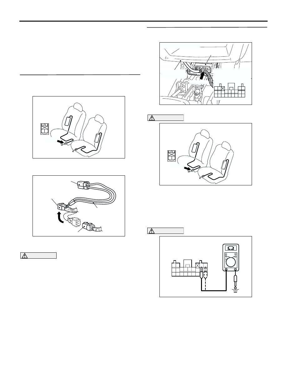
STEP 1. Check the side air bag module (RH). 
(Check whether the diagnosis code is reset.)
(1) Disconnect the negative battery terminal.

(2) Disconnect the side air bag module (RH) 

connector D-40.

(3) Connect special tool dummy resistor (MB991865) 

to special tool resistor harness (MB991866).

CAUTION

Do not insert a test probe into the terminal from 
its front side directly as the connector contact 
pressure may be weakened.
(4) Insert special tool (MB991866) into the D-40 

harness side connector by backprobing.

(5) Connect the negative battery terminal.
(6) Erase the diagnosis code memory, and check the 

diagnosis code.

Q: Is diagnosis code 76 set?

YES : 

Go to Step 2.

NO : 

Replace the seat back assembly of the front 
seat (RH) (Refer to GROUP 52A 

 Front 

Seat 

P.52A-33

). Then go to Step 3.

STEP 2. Measure the resistance at the SRS-ECU 
connector C-114.

(1) Disconnect SRS-ECU connector C-114.

DANGER

To prevents the air bag from deploying 
unintentionally, disconnect the side air bag 
module (RH) connector D-40 to short the 
squib circuit.

(2) Disconnect side air bag module (RH) connector 

D-40.

CAUTION

Do not insert a test probe into the terminal from 
its front side directly as the connector contact 
pressure may be weakened.

AC202027

Connector: D-40

AM

D-40 (R)

2 1

Harness side
connector
(front view)

AC301039AB

MB991865 (Dummy
resistor : 3 

Ω)

D-40 Harness side
connector

D-40 Side air bag
module (RH) connector

MB991866
(Resistor harness)

AC301661

Connector: C-114

AE

SRS-ECU

C-114 (Y)

Center lower
panel

Harness side
connector 
(front view)

40

23

24

41

32

42

33

31

29
38

39

30

37

28

21

22

35

26

36

27

34

25

AC202027

Connector: D-40

AM

D-40 (R)

2 1

Harness side
connector
(front view)

34 35 36 37 38 39 40 41 42

25 26 27 28 29 30 31 32 33

21 22

23 24

AC301045AB

C-114 Harness side
connector (rear view)

TROUBLESHOOTING

SUPPLEMENTAL RESTRAINT SYSTEM (SRS)

52B-136

(3) Measure the resistance between C-114 harness 

side connector terminals 23, 24 and body earth.

OK: Open circuit

Q: Is the check result normal?

YES : 

Erase the diagnosis code memory, and 

check the diagnosis code. If diagnosis code 
76 sets, replace the SRS-ECU (Refer to 

P.52B-178

). Then go to Step   .

NO : 

Repair the harness wires between 
SRS-ECU connector C-114 (terminal No.23 
and 24) and side air bag module (RH) 
connector D-40 (terminal No.2 and 1). Then 
go to Step 3.

STEP 3. Check whether the diagnosis code is 
reset.

Q: Is diagnosis code 76 set?

YES : 

Return to Step 1.

NO : 

The procedure is complete (If no 
malfunctions are found in all steps, an 
intermittent malfunction is suspected. Refer 
to GROUP 00 

 How to Use 

Troubleshooting/Inspection Service Points 

P.00-6

).

TROUBLESHOOTING

SUPPLEMENTAL RESTRAINT SYSTEM (SRS)

52B-137

Code No.79: Side impact sensor (LH) communication error Code No.93: Side impact sensor (LH) 
communication impossible

OPERATION
The side impact sensor includes an analog G sensor 
and CPU, etc. The CPU monitors the analog G 
sensor output signal. If the CPU judges that the side 
air bags should be deployed, it sends a fire signal to 
the SRS-ECU to deploy the side air bags. Besides 
that, the CPU diagnoses the internal components of 
the side impact sensor. If a malfunction occurs, it 
requests the SRS-ECU to set a diagnosis code.

DIAGNOSIS CODE SET CONDITIONS
These diagnosis codes are set if communication 
between the side impact sensor (LH) and the 
SRS-ECU is not possible or communication is faulty.

PROBABLE CAUSES

Damaged wiring harnesses or connectors

Malfunction of the side impact sensor (LH)

Malfunction of the SRS-ECU

Wire colour code
B : Black     LG : Light green     G : Green     L : Blue     W : White     Y : Yellow     SB : Sky blue
BR : Brown     O : Orange     GR : Gray     R : Red     P : Pink     V : Violet   

CONSTANT
VOLTAGE CIRCUIT

CPU

ANALOG
G SENSOR

INTERFACE
CIRCUIT

MICROCOMPUTER

SIDE IMPACT
SENSOR (LH)

SRS-ECU

Side Impact Sensor(LH) Power Supply Circuit

TROUBLESHOOTING

SUPPLEMENTAL RESTRAINT SYSTEM (SRS)

52B-138

DIAGNOSIS PROCEDURE

STEP 1. Check the side impact sensor (LH). 
(Check whether the diagnosis code is reset.)
(1) Disconnect the negative battery terminal.
(2) Replace the side impact sensor (LH) with the side 

impact sensor (RH).

(3) Connect the negative battery terminal.
(4) Erase diagnosis code memory, and check the 

diagnosis code.

Q: Is diagnosis code 89 or 96 set?

YES : 

Replace the side impact sensor (LH) with a 

new one (Refer to 

P.52B-186

). Then go to 

Step 3.

NO : 

Go to Step 2.

STEP 2. Check the harness wires for open circuit 
or short circuit between SRS-ECU connector 
C-114 (terminal No.34 and 36) and side impact 
sensor (LH) connector D-27 (terminal No.1 and 
2).

AC301661

Connector: C-114

AE

SRS-ECU

C-114 (Y)

Center lower
panel

Harness side
connector 
(front view)

40

23

24

41

32

42

33

31

29
38

39

30

37

28

21

22

35

26

36

27

34

25

AC201281

Connector: D-27

D-27 

Front seat belt

Front seat

AE

1

2

Harness side
connector
(front view)


Content   ..  382  383  384  385   ..