Mitsubishi Outlander (2003+). Manual - part 348
 

  Index      Mitsubishi     Mitsubishi Outlander - service repair manual 2003 year


Search            


Content   ..  346  347  348  349   ..


Mitsubishi Outlander (2003+). Manual - part 348


FRONT SEAT ASSEMBLY

INTERIOR

52A-31

INSTALLATION SERVICE POINT

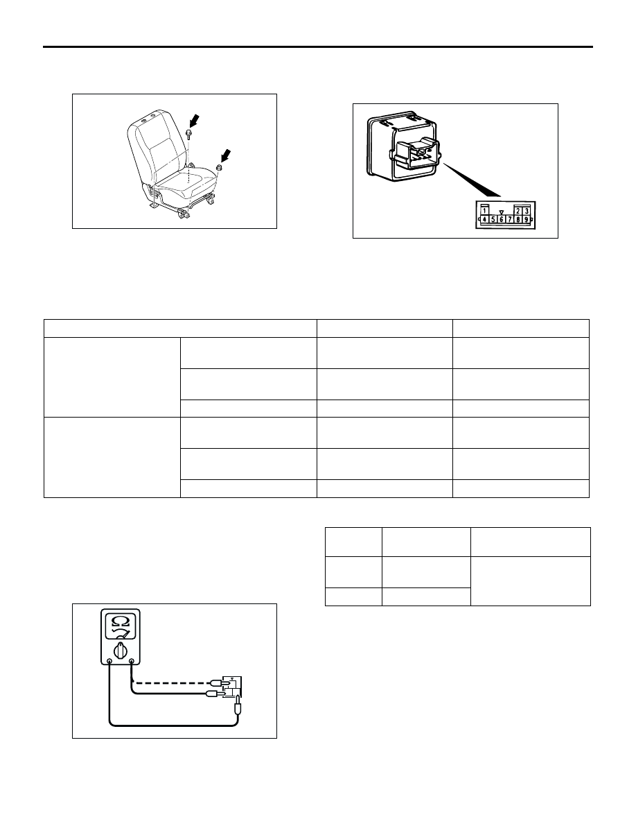
>>A<< FRONT SEAT ASSEMBLY INSTALLATION

1. Temporarily tighten the nuts and bolts in all 

mounting locations shown in the illustration with 
no load applied to the front seat cushion and 
check the operation of the seat slide.

2. Tighten the nuts and bolts in all mounting 

locations to the specified torque.

INSPECTION

M1522005500061

HEATED SEAT SWITCH CHECK

1. Check for continuity between terminals.

2. Check that the indicator is lighted at HI or LO 

when battery voltage is supplied to terminal 5, and 
terminal 8 is grounded.

3. Check that indicator is lighted when battery 

voltage is supplied to terminals 2 and 6.

SEAT CUSHION HEATER CHECK 

Measure the resistance between terminals. 

Standard value:

AC301696 AB

ACX00625

Switch position

Tester connection

Specified condition

Driver's seat side

HI

1 - 3, 1 - 5, 1 - 8, 3 - 5, 3 - 
8, 5 - 8

Less than 2 ohms

OFF

1 - 3, 1 - 5, 1 - 8, 3 - 5, 3 - 
8, 5 - 8

Open circuit

LO

3 - 5, 3 - 8, 5 - 8

Less than 2 ohms

Front passenger's seat 
side

HI

4 - 5, 4 - 8, 4 - 9, 5 - 8, 5 - 
9, 8 

 9

Less than 2 ohms

OFF

4 - 5, 4 - 8, 4 - 9, 5 - 8, 5 - 
9, 8 - 9

Open circuit

LO

5 - 8, 5 - 9, 8 - 9

Less than 2 ohms

1

2 3

AC200099

Measured 
terminals

Resistance 
value

Note

 3

Approximately 
4.8 


±

 10 %

At room temperature 
20 

°

C

 3

5.2 


±

 10 %

FRONT SEAT ASSEMBLY

INTERIOR

52A-32

SEATBACK HEATER CHECK 

Measure the resistance between terminals. 

Standard value: Approximately 4.8 


±

 10 % 

(At room temperature 20 

°

C)

HEATED SEAT RELAY CONTINUITY 
CHECK

1
2

AC200100

Battery voltage

Tester 
connection

Specified 
condition

Not applied

1 - 4

Open circuit

Connect 
terminal 3 to the 
positive battery 
terminal

Connect 
terminal 2 to the 
negative battery 
terminal

1 - 4

Less than 2 
ohms

1

4

3

2

1
3

2
4

AC300127

Junction block

Heated seat relay

AB

FRONT SEAT ASSEMBLY

INTERIOR

52A-33

DISASSEMBLY AND REASSEMBLY

M1522001500490

<L.H. DRIVE VEHICLES>

AC309456

Section A – A

27

10, 11

Claw

AB

12

20 15

17 16

21

18

19

18

4

13

14

9

6

7

8

5

1

3

2

10

24

25

27

24

11

22

26

23

7.6 ± 0.7 N·m

44 ± 10 N·m

A

A

A

12 ± 2 N·m

44 ± 10 N·m

A

NOTE
         : Claw position

N

N

Disassembly steps

1.

Reclining knob

2.

Pin

3.

Height adjuster knob

4.

Heater harness assembly 
<Vehicles with heated seat>

5.

Front seat cushion assembly

6.

Front seat cushion cover

7.

Front seat cushion pad

8.

Front seat cushion frame

9.

Seat cushion heater <Vehicles with 
heated seat>

10. Reclining cover
11. Shield cover
12. Front seatback assembly
13. Lumbar support cap

14. Lumbar support lever

<<A>>

15. Headrest guide
16. Front seatback cover
17. Front seatback pad
18. Lumber support clip
19. Lumber support
20. Front seatback frame
21. Seatback heater <Vehicles with 

heated seat>

22. Inner seat belt
23. Shaft
24. Pin
25. Slide handle
26. Shaft protector
27. Seat slide adjuster

Disassembly steps (Continued)

FRONT SEAT ASSEMBLY

INTERIOR

52A-34

<R.H. DRIVE VEHICLES>

AC309458

NOTE
         : Claw position

Section A – A

Claw

22

8, 9

9 ± 2 N·m

44 ± 10 N·m

12 ± 2 N·m

A

A

A

A

44 ± 10 N·m

10

14

15

13

16

11

12

4

5

6

7

1

2

3

8

19

20

22

19

21

18

17

9

AB

Disassembly steps

1.

Reclining knob

2.

Pin

3.

Height adjuster knob

4.

Front seat cushion assembly

5.

Front seat cushion cover

6.

Front seat cushion pad

7.

Front seat cushion frame

8.

Reclining cover

9.

Shield cover

10. Front seatback assembly
11. Pin (Driver’s side)

12. Arm rest assembly (Driver’s side)

<<A>>

13. Headrest guide
14. Front seatback cover
15. Front seatback pad
16. Front seatback frame
17. Inner seat belt
18. Shaft
19. Pin
20. Seat slide handle
21. Shaft protector
22. Seat slide adjuster

Disassembly steps (Continued)


Content   ..  346  347  348  349   ..