Mitsubishi Outlander (2003+). Manual - part 343
 

  Index      Mitsubishi     Mitsubishi Outlander - service repair manual 2003 year


Search            


Content   ..  341  342  343  344   ..


Mitsubishi Outlander (2003+). Manual - part 343


INSTRUMENT PANEL ASSEMBLY

INTERIOR

52A-11

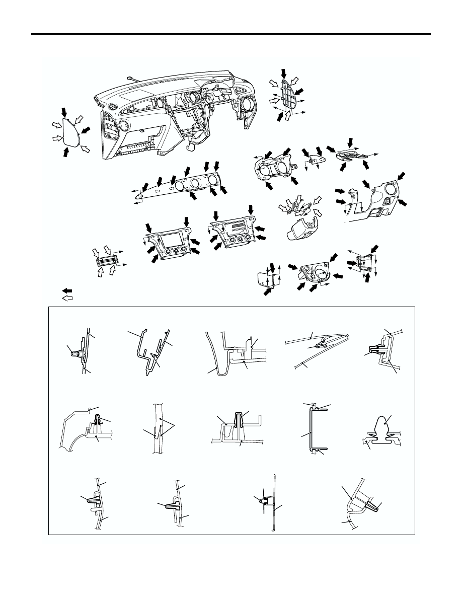
CLIP AND CLAW POSITIONS

AC309410AB

A

A

B

B

NOTE
(1)         : Clip Position
(2)         : Claw Position

L

L

L

L

N

M

M

L

K

K

N

L

J

J

F

F

G

G

C

C

D

D

H

H

H

H

I

I

E

E

Section A – A

Section B – B

Section C – C

Section D – D

Section E – E

Section F – F

Section G – G

Section H – H

Section I – I

Section J – J

Section K – K

Section L – L

Section M – M

Section N – N

Clip

Instrument 
panel side 
cover

Instrument panel 
assembly

Claw

Instrument panel 
assembly

Instrument 
panel side 
cover

Clip

Instrument panel 
assembly

Instrument lower 
panel

Claw

Column 
cover

Meter bezel 

Instrument panel 
driver's side garnish

Claw

Clip

Instrument panel 
assembly

Center panel

Instrument panel 
assembly

Clip

Meter bezel

Claw

Claw

Radio plug

Center panel

Clip

JB cover

Clip

Instrument panel 
center console

Instrument panel 
garnish

Clip

Instrument panel 
assembly

Instrument panel 
console side cover

Clip

Instrument panel 
center console

Instrument panel 
console side cover

Clip

Instrument panel 
console side cover

Clip

Instrument panel 
center console

Gear shift lever panel

INSTRUMENT PANEL ASSEMBLY

INTERIOR

52A-12

REMOVAL SERVECE POINT

<<A>> INSTRUMENT PANEL AIR OUTLET 
REMOVAL

The instrument panel air outlet may remain on the 
instrument panel side when disassembling the lower 
panel of the instrument panel and the instrument 
panel garnish. Carefully disassemble the parts 
remaining on the instrument panel side to prevent 
the ball and spring from falling. Assemble the ball 
and spring according to the figure to the left if the fall 
off.

AC103520AB

Ball

Spring

INSTRUMENT PANEL ASSEMBLY

INTERIOR

52A-13

DISASSEMBLY AND REASSEMBLY

M1521001900387

<R.H. DRIVE VEHICLES>

AC212542

6

14

3

4

7

8

15

10

12

13

11

1

2

3

5

d

d

d

d

d

d

d

d

d

d

a

d

d

d

d

d

d

d

d

d

d

d

d

e

d

g

d

AC

9

d

Disassembly steps

1.

Passenger’s side air bag module 
bracket 

2.

Passenger’s side air bag module

3.

Side defroster duct

4.

Defroster nozzle assembly

5.

Distribution duct

6.

Meter bracket

7.

Instrument panel garnish bracket

8.

Instrument panel reinforcement

9.

Centre panel bracket

10. Centre cover driver’s side
11. Glove box striker
12. Instrument panel undercover 

passenger’s side

13. Side air outlet assembly (L.H.)
14. Instrument panel holder
15. Instrument panel

Photo sensor (Refer to GROUP 
55B, Sensors 

P.55B-103

).

Disassembly steps (Continued)

FLOOR CONSOLE ASSEMBLY

INTERIOR

52A-14

FLOOR CONSOLE ASSEMBLY

REMOVAL AND INSTALLATION

M1521002200325

<L.H. DRIVE VEHICLES>

AC301787

NOTE
         : Clip position

Section A – A

B

B

D

D

A

A

C

C

11

11

2

6

12

3

7

5

4

1

8

9

10

11 ± 2 N·m

11 ± 2 N·m

13

Section B – B

Section C – C

Section D – D

Clip

Clip

11

11

Clip

Clip

3

9

AB

C

C

13

12

12

12

Removal steps

1.

Shift knob

2.

Floor console panel cover

3.

Front floor console panel

4.

Harness connector <Vehicles with 
heated seat>

5.

Heated seat switch <Vehicles with 
heated seat>

6.

Coin holder <Vehicles without 
heated seat>

7.

Ashtray

8.

Shift lever cover

9.

Rear floor console assembly

10. Rear floor console bracket
11. Front floor console lower side cover
12. Front floor console
13. Front floor console bracket

Removal steps (Continued)


Content   ..  341  342  343  344   ..