Mitsubishi Outlander (2003+). Manual - part 281
 

  Index      Mitsubishi     Mitsubishi Outlander - service repair manual 2003 year


Search            


Content   ..  279  280  281  282   ..


Mitsubishi Outlander (2003+). Manual - part 281


ABS SENSOR

ANTI-SKID BRAKING SYSTEM (ABS)

35B-67

ABS SENSOR

REMOVAL AND INSTALLATION

M1352020700038

REMOVAL SERVICE POINT

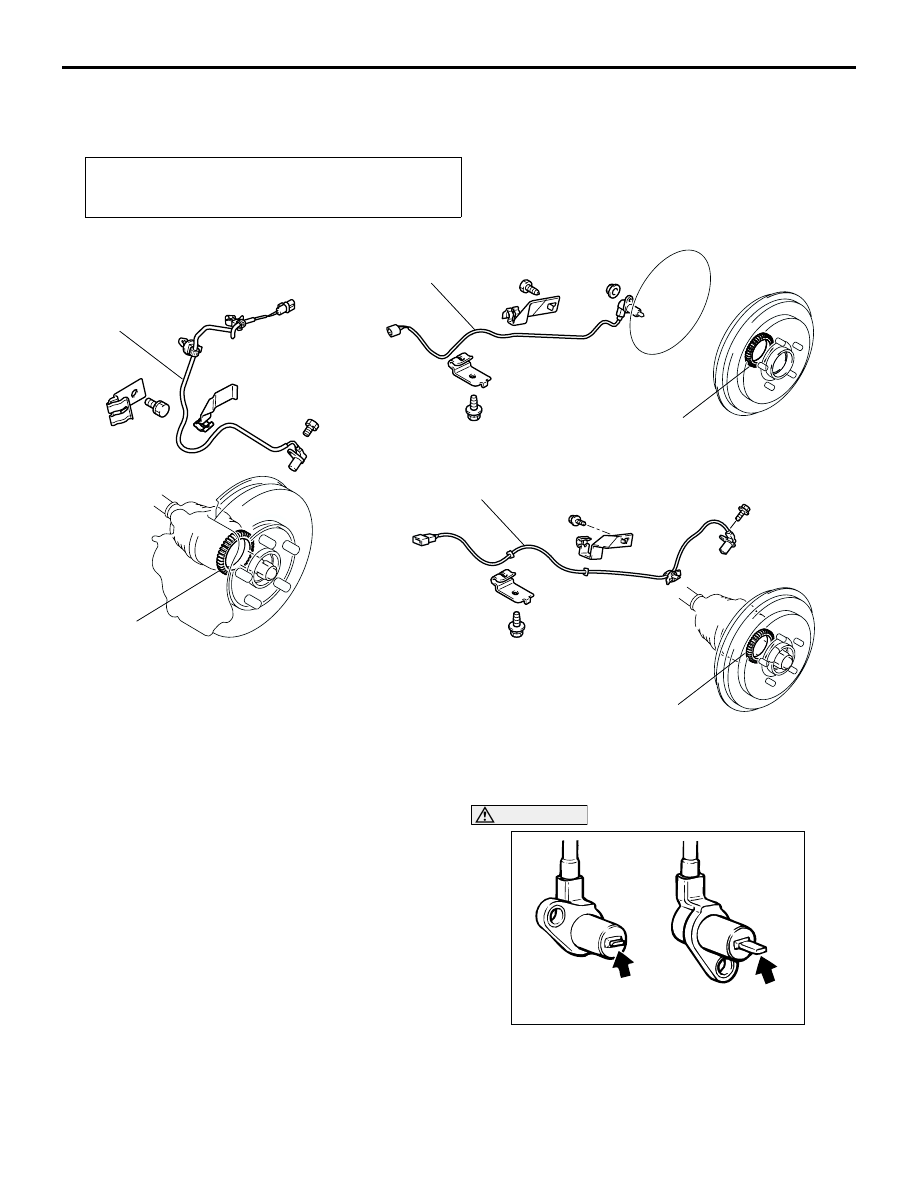
<<A>> FRONT ABS SENSOR/REAR ABS 
SENSOR REMOVAL

CAUTION

Be careful when handling the projection at the tip 
of the ABS sensor and the toothed edge of the 
ABS rotor so as not to damage them by 
contacting other parts.

Post-installation Operation

ABS Sensor Output Voltage Measurement (Refer to 

P.35B-59

).

AC301105AB

<Front>

<Rear (2WD)>

1

2

4

3

3

4

<Rear (4WD)>

Front ABS sensor removal steps

<<A>>

1.

Front ABS sensor

2.

Front ABS rotor (Refer to GROUP 
26, Driveshaft 

P.26-20

).

Rear ABS sensor removal steps

<<A>>

3.

Rear ABS sensor

4.

Rear ABS rotor (Refer to GROUP 
27A, Rear Hub Assembly 

P.27A-5


for 2WD, or GROUP 27B, 
Driveshaft 

P.27B-13

 for 4WD).

AC100242 AE

<Front, Rear (4WD)>

<Rear (2WD)>

ABS SENSOR

ANTI-SKID BRAKING SYSTEM (ABS)

35B-68

INSPECTION

M1352020800035

ABS SENSOR CHECK

1. Check whether any metallic foreign material has 

adhered to the projection at the ABS sensor tip. 
Remove any foreign material. Also check whether 
the pole piece is damaged. Replace it with a new 
one if it is damaged.
NOTE: The projection can become magnetized 
due to the magnet inside the ABS sensor, causing 
foreign material to easily adhere to it. The 
projection may not be able to correctly sense the 
wheel rotation speed if foreign matter is on it or if it 
is damaged.

2. Measure the resistance between the ABS sensor 

terminals.

Standard value: 1.24 

 1.64 k

3. If the internal resistance of the ABS sensor is not 

within the standard value, replace it with a new 
ABS sensor.

4. Remove all connections from the ABS sensor. 

The circuit should be open between terminals (1) 
and (2) and the body of the ABS sensor. If the 
circuit is not open, replace with a new ABS 
sensor.

5. Check the ABS sensor cable for breakage, 

damage or disconnection. Replace with a new 
one if a problem is found.
NOTE: When checking for cable damage, remove 
the cable clamp part from the body and then 
gently bend and pull the cable near the clamp.

TOOTHED ABS ROTOR CHECK

Check whether the ABS rotor teeth are broken or 
deformed. Replace the BJ assembly of the 
driveshaft, or the ABS rotor (2WD-rear side), 
respectively, if the teeth are damaged or deformed.

AC201428AD

<Rear>

<Front>

ACX01120

AC000965

G-SENSOR

ANTI-SKID BRAKING SYSTEM (ABS)

35B-69

G-SENSOR

REMOVAL AND INSTALLATION

M1352010100251

CAUTION

Do not drop or apply a shock on the G-sensor.

INSPECTION

M1352018000065

G-SENSOR CHECK

1. Disconnect the G-sensor connector and connect 

special tool Test Harness Set (MB991348), 
between the disconnected connectors.

2. Turn the ignition switch to the "ON" position, and 

then read the voltage between terminals number 
2 and number 3.

Standard Value: 2.4 

 2.6 V

3. With special tool Test Harness Set (MB991348) 

connected, rotate so that the arrow faces straight 
down. Read output voltage between terminals 
number 2 and number 3.

Standard Value: 1.0 

 4.0 V

4. If the voltage deviates from the standard value, 

make sure that nothing is wrong with the power 
supply wire and earth wire and then replace the 
G-sensor.

Pre-removal and Post-installation Operation

Rear Floor Console Assembly Removal and Installation 

(Refer to GROUP 52A, Floor Console Assembly 

P.52A-14

).

AC200354

AC

G-sensor

AC103662AJ

MB991348

Connector: D-35
(Harness side)

Label

Label

NOTES


Content   ..  279  280  281  282   ..