Mitsubishi Outlander (2003+). Manual - part 169
 

  Index      Mitsubishi     Mitsubishi Outlander - service repair manual 2003 year


Search            


Content   ..  167  168  169  170   ..


Mitsubishi Outlander (2003+). Manual - part 169


INPUT SHAFT

MANUAL TRANSMISSION OVERHAUL

22B-29

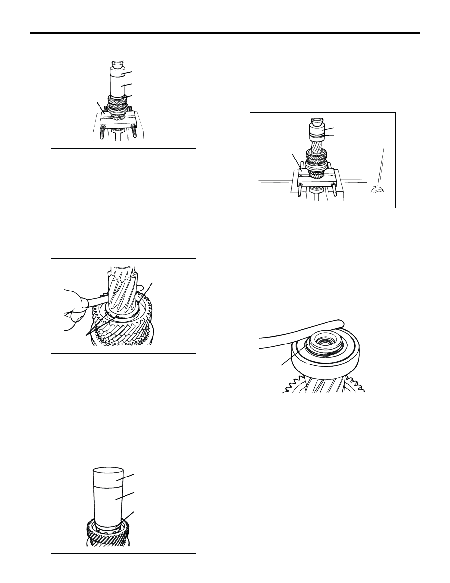
>>I<< 5TH SPEED GEAR INSTALLATION

1. Using special tool Bearing remover (MD998801), 

support the 2nd speed gear portion of the input 
shaft, and then set them on the press.

2. Using special tools, install the 5th speed gear onto 

the input shaft with the press.

Installer cap (MD998812)

Installer-100 (MD998813)

Installer adapter (MD998824)

>>J<< THRUST PLATE INSTALLATION

1. Install the thickest thrust plates that can be fitted 

in the groove of the input shaft. Install the thrust 
plate so the surface stamped with the 
identification mark is facing up. 

2. Make sure that the 5th speed gear end play meets 

the standard value.

Standard value: 0 

 0.09 mm

>>K<< THRUST PLATE STOPPER INSTALLATION

Install the thrust plate stopper by pressing special 
tools, by hand. Make sure that it is not tilted.

Installer cap (MD998812)

Installer-100 (MD998813)

Installer adapter (MD998824)

>>L<< BALL BEARING INSTALLATION

1. Using special tool Bearing remover (MD998801), 

support the 2nd speed gear portion of the input 
shaft, and then set them on the press.

2. Using special tools, install the ball bearing onto 

the input shaft with the press. 

Installer cap (MD998812)

Installer adapter (MD998818)

>>M<< SNAP RING INSTALLATION

1. Install the thickest snap ring that can be fitted in 

the groove of the input shaft.

2. Make sure that the rear bearing end play meets 

the standard value.

Standard value: 0 

 0.12 mm

AK204248

MD998812

MD998813

MD998824

MD998801

AB

AK204249AB

Surface stamped
with identification
mark

Thrust plate

AK204294

MD998812

MD998813

MD998824

AB

AK204250

MD998812
MD998818

MD998801

AC

AK204251

Snap ring

AB

INPUT SHAFT

MANUAL TRANSMISSION OVERHAUL

22B-30

INSPECTION

M1222001700095

INPUT SHAFT

1. Check the outside diameter of the needle bearing 

mounting portion for damage, abnormal wear and 
seizure.

2. Check the splines for damage and wear.
3. Check that the helical gear teeth surfaces are not 

damaged or worn.

NEEDLE ROLLER BEARING
1. Combine the needle roller bearing with the input 

shaft or bearing sleeve and gear, and check that it 
rotates smoothly without noise or play.

2. Check the needle roller bearing cage for 

deformation.

SYNCHRONIZER RING

1. Check the clutch gear teeth for damage and 

broken.

2. Check internal surface for damage, wear and 

broken threads.

3. Force the synchronizer ring toward the clutch gear 

and check clearance "A". If "A" is less than the 
limit, replace the synchronizer ring.

Minimum limit: 0.5 mm

SYNCHRONIZER SLEEVE AND HUB

1. Combine the synchronizer sleeve and hub, and 

check that they slide smoothly.

2. Check that the sleeve is free from damage at its 

inside splines ends.

SYNCHRONIZER SPRING
Check that the spring is not sagging, deformed or 
broken.

AK204201AB

AK204298AB

AK204307

A

Gear

Synchronizer
ring

AB

AK204217

Sleeve

Hub

AB

INPUT SHAFT

MANUAL TRANSMISSION OVERHAUL

22B-31

SPEED GEARS

1. Check that the helical and clutch gear tooth 

surfaces are not damaged or worn.

2. Check that the synchronizer cone surfaces are 

not roughened, damaged or worn.

3. Check that the gear inside diameter and front and 

rear surfaces are not damaged and worn.

AK204299AB

OUTPUT SHAFT

MANUAL TRANSMISSION OVERHAUL

22B-32

OUTPUT SHAFT

DISASSEMBLY AND REASSEMBLY

M1222002200156

AK204392

20

22

24

4

26

1

19

18

21

23

13

27

29

25

28

30

31

32

33

36

35

34

5

2

3

4

6

7

8

9

11

14 10

12

17

15

16

13

AB

Apply gear oil to all
moving parts before
installation.

Disassembly steps

>>Q<<

1.

Snap ring

<<A>>

>>P<<

2.

Ball bearing

<<B>>

>>O<<

3.

Reverse gear sleeve

4.

Needle roller bearing

5.

Reverse gear

>>M<<

6.

Synchronizer ring

>>L<<

7.

Synchronizer spring

>>F<<

8.

Synchronizer sleeve

<<C>>

>>N<<

9.

5th speed-reverse synchronizer 
hub

>>M<<

10. Synchronizer ring

>>L<<

11. Synchronizer spring
12. 5th speed gear
13. Needle roller bearing

>>K<<

14. 5th speed gear sleeve

>>J<<

15. 4th speed gear

>>I<<

16. Snap ring

<<D>>

>>H<<

17. 3rd speed gear

18. 2nd speed gear
19. Needle roller bearing

<<E>>

>>G<<

20. 2nd speed gear sleeve
21. Inner synchronizer ring
22. Synchronizer cone
23. Outer synchronizer ring

>>D<<

24. Synchronizer spring

>>F<<

25. Synchronizer sleeve

>>E<<

26. 1st-2nd speed synchronizer hub
27. Outer synchronizer ring

>>D<<

28. Synchronizer spring
29. Inner synchronizer ring
30. Synchronizer cone
31. 1st speed gear
32. Needle roller bearing

<<F>>

>>C<<

33. 1st speed gear sleeve

>>B<<

34. Snap ring

Disassembly steps (Continued)


Content   ..  167  168  169  170   ..