Mitsubishi Montero Sport (2004+). Manual - part 776
MASTER CYLINDER ASSEMBLY AND BRAKE BOOSTER
TSB Revision
BASIC BRAKE SYSTEM
35A-29
INSTALLATION SERVICE POINTS
.
>>A<< VACUUM HOSE CONNECTION
Insert securely and completely until the vacuum hose at the
engine side contacts the edge of the hexagonal part of the fit-
ting, and then secure by using the hose clamp.
.
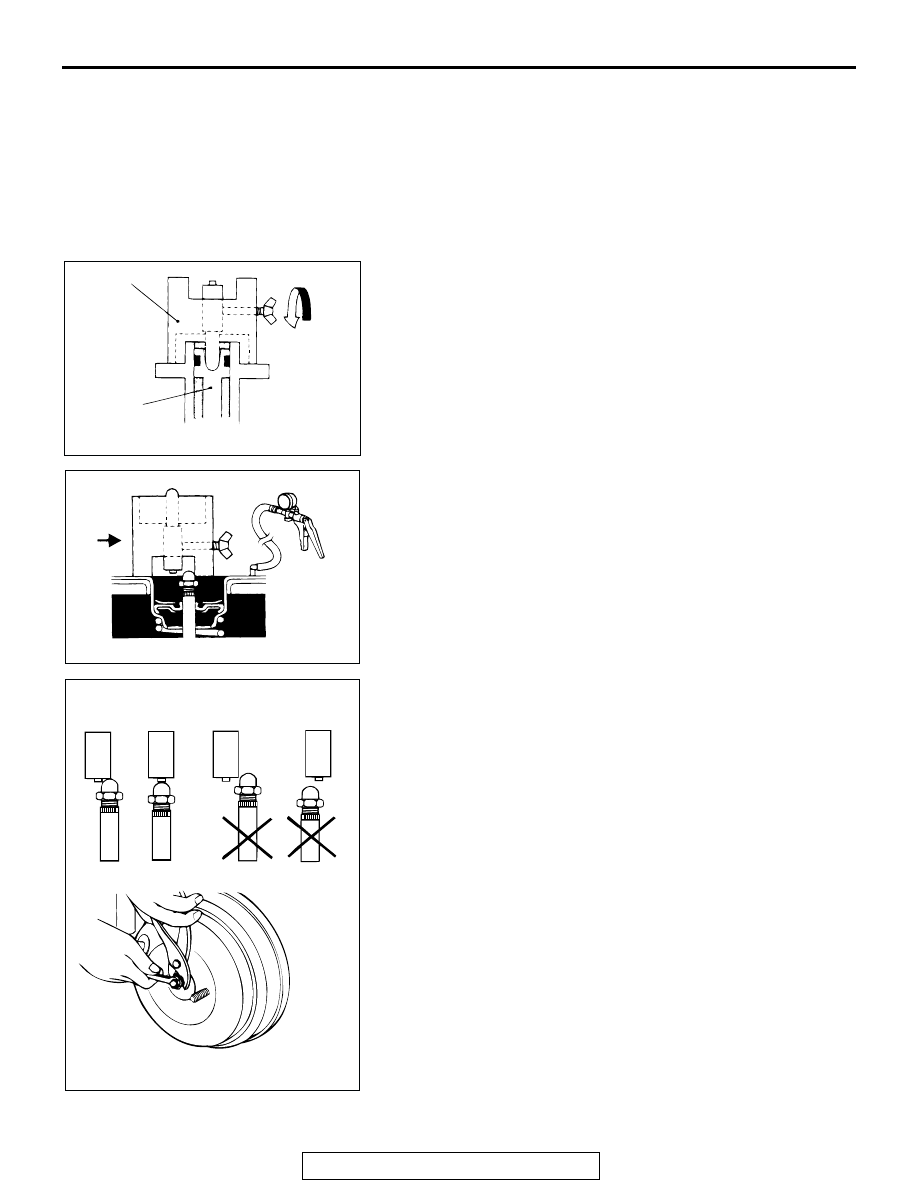
>>B<< CLEARANCE ADJUSTMENT BETWEEN BRAKE
BOOSTER PUSHROD AND PRIMARY PISTON
1. Set the special tool MB991714 in the master cylinder.
2. Set the special tool shaft to a position where it lightly
contacts the master cylinder's piston.
3. Turn the thumb bolt to fix the shaft.
4. Apply a negative pressure of
−66.7 kPa (19.6 in.Hg) on the
brake booster, using a hand vacuum pump.
5. Reverse the special tool MB991714 to shift it from the center
of the brake booster.
6. Slide the special tool MB991714 toward the center, and
confirm that the protrusion of the shaft contacts the end of
the brake booster pushrod as shown in drawing A on the
left.
If the state is as shown in drawings B and C on the left,
adjust the pushrod length with the following steps to achieve
the state shown in A.
B: If a section other than the shaft protrusion is contacted,
shorten the pushrod.
C: If there is no contact with the shaft, lengthen the pushrod.
AC103708 AB
MB991714
MASTER
CYLINDER
AC004418 AB
AC004419 AB
OK
OK
NOT OK
NOT OK
A
A
B
C