Mitsubishi Montero Sport (2004+). Manual - part 709


  Index      Mitsubishi     Mitsubishi Montero Sport - service repair manual 2004 year


Search            


Content   ..  707  708  709  710   ..


Mitsubishi Montero Sport (2004+). Manual - part 709


AUTOMATIC TRANSMISSION DIAGNOSIS

TSB Revision

AUTOMATIC TRANSMISSION

23A-401

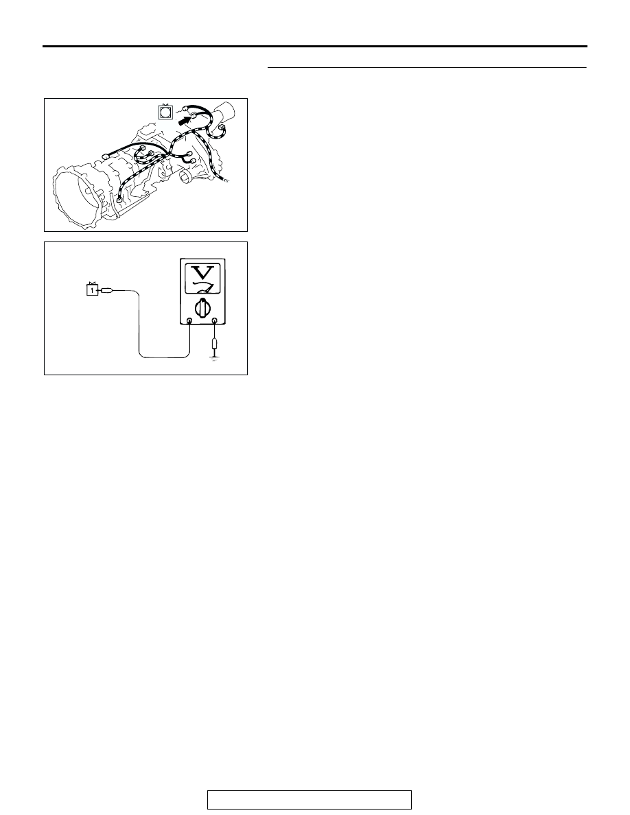
STEP 3. Measure the switch output voltage at transfer low 
detection switch connector B-17.

(1) Disconnect connector B-17 and measure at the harness 

side.

(2) Turn the ignition switch to the "ON" position.

(3) Measure the voltage between terminal 1 and ground.

• The voltage should measure battery positive voltage.

(4) Turn the ignition switch to the "LOCK" (OFF) position.
Q: Is the measured voltage battery positive voltage?

YES : Go to Step 10.
NO :  Go to Step 4.

AC103769

CONNECTOR: B-17

AC

B-17

1

AC002217

AE

B-17 HARNESS CONNECTOR:
COMPONENT SIDE 

AUTOMATIC TRANSMISSION DIAGNOSIS

TSB Revision

AUTOMATIC TRANSMISSION

23A-402

STEP 4. Measure the switch output voltage at PCM 
connector C-92 by backprobing.

(1) Do not disconnect connector C-92.
(2) Turn the ignition switch to the "ON" position.

(3) Measure the voltage between terminal 112 and ground by 

backprobing.

• The voltage should measure battery positive voltage.

(4) Turn the ignition switch to the "LOCK" (OFF) position.
Q: Is the measured voltage battery positive voltage?

YES : Go to Step 5.
NO :  Go to Step 7.

AC202317

PCM

120

107

119

106

129 130

118

105

117

114115116

126127128

104

111

103

112

108

101102

109110

121122123

124

113

125

CONNECTOR: C-92

C-92 (GR)

AB

AC002218AD

C-92 HARNESS CONNECTOR:
HARNESS SIDE

AUTOMATIC TRANSMISSION DIAGNOSIS

TSB Revision

AUTOMATIC TRANSMISSION

23A-403

STEP 5. Check PCM connector C-92 and intermediate 
connector C-96 for loose, corroded or damaged terminals, 
or terminals pushed back in the connector.

Q: Are the connectors and terminals in good condition?

YES : Go to Step 6.
NO :  Repair or replace the damaged components. Refer to 

GROUP 00E, Harness Connector Inspection 

P.00E-2

.

AC202317

PCM

120

107

119

106

129 130

118

105

117

114115116

126127128

104

111

103

112

108

101102

109110

121122123

124

113

125

CONNECTOR: C-92

C-92 (GR)

AB

AC202318

22

9 10

20

19

6 7 8

21

17

1516

5

14

1213

3

2

4

18

11

1

AB

CONNECTOR: C-96

C-96

AUTOMATIC TRANSMISSION DIAGNOSIS

TSB Revision

AUTOMATIC TRANSMISSION

23A-404

STEP 6. Check harness for open circuit between transfer 
low detection switch connector B-17 terminal 1 and PCM 
connector C-92 terminal 112.

Q: Is the harness wire in good condition?

YES : Go to Step 9.
NO :  Repair or replace the harness wire.

AC103769

CONNECTOR: B-17

AC

B-17

1

AC202317

PCM

120

107

119

106

129 130

118

105

117

114115116

126127128

104

111

103

112

108

101102

109110

121122123

124

113

125

CONNECTOR: C-92

C-92 (GR)

AB


Content   ..  707  708  709  710   ..