Mitsubishi Montero Sport (2004+). Manual - part 579


  Index      Mitsubishi     Mitsubishi Montero Sport - service repair manual 2004 year


Search            


Content   ..  577  578  579  580   ..


Mitsubishi Montero Sport (2004+). Manual - part 579


THEFT ALARM

TSB Revision

CHASSIS ELECTRICAL

54-303

.

CIRCUIT OPERATION
Refer to ETACS-ECU Power Supply and Scan Tool 
Communication Circui

P.54-285

. The ETACS-ECU 

is always energized by the battery.

.

TECHNICAL DESCRIPTION (COMMENT)
If that power supply circuit is defective, the circuit 
flowing through the ignition switch (IG1) will function 
as a backup circuit. In this case, the following is at 
"LOCK" (OFF) position.

• Light reminder tone alarm function

• Ignition key reminder tone alarm function

• Central door locking system

• Dome light dimming function

• Theft alarm system

.

TROUBLESHOOTING HINTS

• Malfunction of the ETACS-ECU 

• Damaged harness wires or connectors 

.

DIAGNOSIS

Required Special Tools:

• MB991223: Test Harness Set
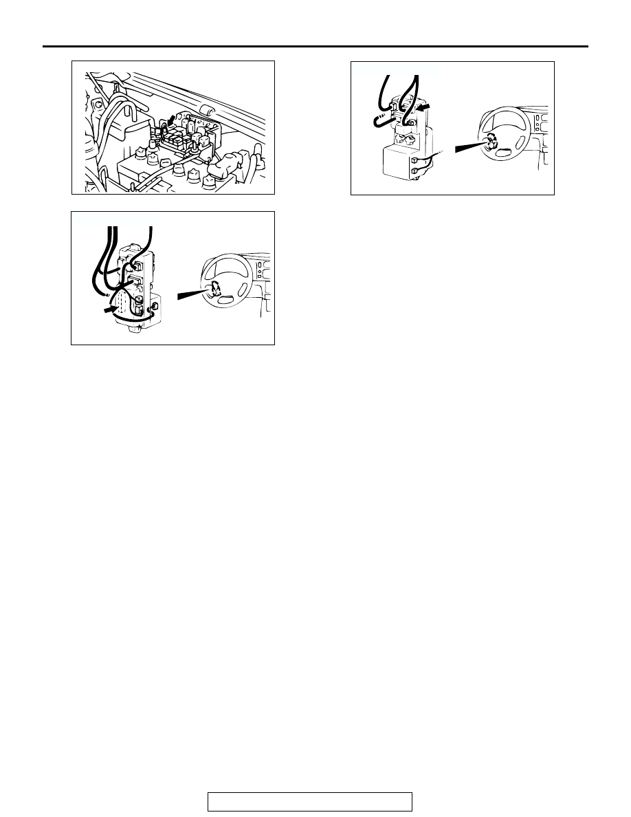
AC003431

CONNECTOR: A-54X

A-54X

AC

AC003432AB

CONNECTOR: D-01

JUNCTION BLOCK

(FRONT)

D-01

AC003445 AE

CONNECTOR: D-11

JUNCTION BLOCK (REAR)

D-11

THEFT ALARM

TSB Revision

CHASSIS ELECTRICAL

54-304

STEP 1. Measure the voltage at ETACS-ECU power supply.

(1) Disconnect ETACS-ECU connector D-11 and measure the 

harness side.

(2) Measure the Voltage between terminal 2 and ground.

• The measured value should be approximately 12 volts 

(battery positive voltage).

Q: Does the measured voltage correspond with this range?

YES : Replace the ETACS-ECU. The functions, which are 

described in the "Technical Description (comment)," 
should work normally.

NO :  Go to Step 2.

STEP 2. Check ETACS-ECU connector D-11 for loose, 
corroded or damaged terminals, or terminals pushed back 
in the connector.

Q: Is ETACS-ECU connector D-11 in good condition?

YES : Go to Step 3.
NO :  Repair or replace it. Refer to GROUP 00E, Harness 

Connector Inspection 

P.00E-2

. The functions, which 

are described in the "Technical Description 
(comment)," should work normally.

STEP 3. Check the harness wires between ETACS-ECU 
connector D-11 (terminal No.2) and fusible link No.8.

AC201084

JUNCTION 
BLOCK (REAR)

D-11

COMPONENT SIDE

AB

CONNECTOR: D-11

1

2

3

4

5

7

9

10

6

8

11

12

AC003996AB

CONNECTOR D-11

(HARNESS SIDE)

AC201084

JUNCTION 
BLOCK (REAR)

D-11

COMPONENT SIDE

AB

CONNECTOR: D-11

AC201084

JUNCTION 
BLOCK (REAR)

D-11

COMPONENT SIDE

AB

CONNECTOR: D-11

THEFT ALARM

TSB Revision

CHASSIS ELECTRICAL

54-305

NOTE: After checking junction block connector D-01 and OD or 
storage connector A-54X, check the wires. If junction block 
connector D-01 and OD or storage connector A-54X are dam-
aged, repair or replace them. Refer to GROUP 00E, Harness 
Connector Inspection 

P.00E-2

.

Q: Are the harness wires between ETACS-ECU connector 

D-11 (terminal No.2) and fusible link No.8 in good 
condition?
YES : 
There is no action to be taken.
NO :  Repair them. The functions, which are described in 

the "Technical Description (comment)," should work 
normally.

AC200774

2

1

CONNECTOR: A-54X

AB

A-54X

AC200778

2

3

4

11 10 9 8 7

1
6

5

12

CONNECTOR: D-01

AB

D-01 COMPONENT SIDE

JUNCTION BLOCK (FRONT)

D-01

THEFT ALARM

TSB Revision

CHASSIS ELECTRICAL

54-306

THEFT ALARM

REMOVAL AND INSTALLATION

M1547001000179

AC002839

1

2

3

AB

REMOVAL STEPS

1. THEFT-ALARM HORN
2. HOOD SWITCH
3. SECURITY INDICATOR


Content   ..  577  578  579  580   ..