Mitsubishi Montero Sport (2004+). Manual - part 527


  Index      Mitsubishi     Mitsubishi Montero Sport - service repair manual 2004 year


Search            


Content   ..  525  526  527  528   ..


Mitsubishi Montero Sport (2004+). Manual - part 527


COMBINATION METER ASSEMBLY AND VEHICLE SPEED SENSOR

TSB Revision

CHASSIS ELECTRICAL

54-95

DIAGNOSIS 

Required Special Tools:

• MB991223: Harness Set

• MB991958: Scan Tool (MUT-III Sub Assembly)

• MB991824: Vehicle Communication Interface (V.C.I.)

• MB991827: MUT-III USB Cable

• MB991911: MUT-III Main Harness B (Vehicles without 

CAN communication system)

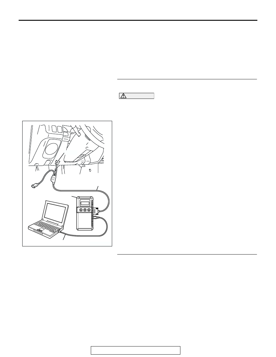
STEP 1. Using scan tool MB991958, read the MFI system 
diagnostic trouble code.

CAUTION

To prevent damage to scan tool MB991958, always turn the 
ignition switch to "LOCK" (OFF) position before connect-
ing or disconnecting scan tool MB991958.
(1) Connect scan tool MB991958 to the data link connector. 
(2) Turn the ignition switch to the "ON" position.
(3) Read the MFI system diagnostic trouble code.
Q: Is MFI system diagnosis code output?

YES : Refer to GROUP 13A, MFI diagnosis 

P.13A-26

.

NO :  Go to Step 2.

STEP 2. Check the speedometer operation.
Q: Does the speedometer work normally?

YES : Refer to Inspection Procedure 1 

P.54-77

NO :  Go to Step 3.

AK303629AB

MB991911

MB991827

MB991824 

16-PIN

COMBINATION METER ASSEMBLY AND VEHICLE SPEED SENSOR

TSB Revision

CHASSIS ELECTRICAL

54-96

STEP 3. Check the combination meter (tachometer) ground 
circuit at combination meter connector C-05.

(1) Disconnect combination meter connector C-05.

(2) Measure the resistance between terminal 13 and ground.

• The measured value should be 2 ohms or less.

Q: Does the measured resistance value correspond with 

this range?
YES : 
Go to Step 6.
NO :  Go to Step 4.

AC2018743

3 2

6 5 4

7

8

9

1110

1

12

1413

CONNECTOR: C-05

C-05 HARNESS CONNECTOR

C-05

AC201843 AB

AC002757

AC

C-05 HARNESS CONNECTOR:
COMPONENT SIDE

COMBINATION METER ASSEMBLY AND VEHICLE SPEED SENSOR

TSB Revision

CHASSIS ELECTRICAL

54-97

STEP 4. Check combination meter connector C-05 for 
loose, corroded or damaged terminals, or terminals 
pushed back in the connector.

Q:  Is combination meter connector C-05 in good 

condition?
YES : 
Go to Step 5.
NO :  Repair or replace it. Refer to GROUP 00E, Harness 

Connector Inspection 

P.00E-2

. The tachometer 

should work normally.

STEP 5. Check the harness wires between combination 
meter connector C-05 (terminal No.14) and ground.

Q: Are the harness wires between combination meter 

connector C-05 (terminal No.14) and ground in good 
condition?
YES : 
There is no action to be taken.
NO :  Repair them. The tachometer should work normally.

AC2018743

3 2

6 5 4

7

8

9

1110

1

12

1413

CONNECTOR: C-05

C-05 HARNESS CONNECTOR

C-05

AC201843 AB

AC2018743

3 2

6 5 4

7

8

9

1110

1

12

1413

CONNECTOR: C-05

C-05 HARNESS CONNECTOR

C-05

AC201843 AB

COMBINATION METER ASSEMBLY AND VEHICLE SPEED SENSOR

TSB Revision

CHASSIS ELECTRICAL

54-98

STEP 6. Check the ignition signal input circuit at 
combination meter connector C-04.

(1) Disconnect combination meter connector C-04.
(2) Start the engine and run at idle.

(3) Measure the voltage between terminal 24 and ground by 

back probing.
The measured value should be approximately 10 volts.

Q: Does the measured voltage correspond with this range?

YES : Repair or replace the combination meter 

(printed-circuit board or speedometer and 
tachometer). 

NO :  Go to Step 7.

STEP 7. Check combination meter connector C-04 for 
loose, corroded or damaged terminals, or terminals 
pushed back in the connector.

Q:  Is combination meter connector C-04 in good 

condition?
YES : 
Go to Step 8.
NO :  Repair or replace it. Refer to GROUP 00E, Harness 

Connector Inspection 

P.00E-2

. The tachometer 

should work normally.

STEP 8. Check the harness wires between combination 
meter connector C-04 (terminal No.24) and ignition switch 

(IG1).

AC201897

21

23

24

27 26 25

22

28

30

31

29

32

CONNECTOR: C-04

AB

C-04: HARNESS SIDE 
CONNECTOR

C-04

AC002756

AC

C-04 HARNESS CONNECTOR:
COMPONENT SIDE

AC201897

21

23

24

27 26 25

22

28

30

31

29

32

CONNECTOR: C-04

AB

C-04: HARNESS SIDE 
CONNECTOR

C-04

AC201897

21

23

24

27 26 25

22

28

30

31

29

32

CONNECTOR: C-04

AB

C-04: HARNESS SIDE 
CONNECTOR

C-04


Content   ..  525  526  527  528   ..