Mitsubishi Montero Sport (2004+). Manual - part 518


  Index      Mitsubishi     Mitsubishi Montero Sport - service repair manual 2004 year


Search            


Content   ..  516  517  518  519   ..


Mitsubishi Montero Sport (2004+). Manual - part 518


IGNITION SWITCH

TSB Revision

CHASSIS ELECTRICAL

54-59

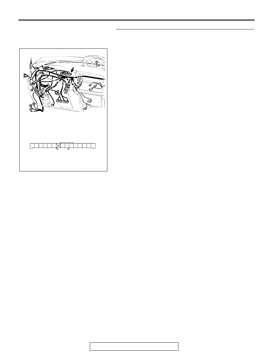
STEP 3. Check combination meter connector C-05 for 
loose, corroded or damaged terminals, or terminals 
pushed back in the connector. 

Q: Is combination meter connector C-05 in good 

condition?
YES : 
Repair or replace them. Refer to GROUP 00E, 

Harness Connector Inspection 

P.00E-2

. Confirm that 

scan tool MB991958 communicates normally.

NO :  Go to Step 4.

AC2018743

3 2

6 5 4

7

8

9

1110

1

12

1413

CONNECTOR: C-05

C-05 HARNESS CONNECTOR

C-05

AC201843 AB

IGNITION SWITCH

TSB Revision

CHASSIS ELECTRICAL

54-60

STEP 4. Check the harness wires between 
immobilizer-ECU connector C-107 and combination meter 
connector C-05.

Q: Are immobilizer-ECU connector C-107 and combination 

meter connector C-05 damaged?
YES : 
Repair or replace them. Refer to GROUP 00E, 

Harness Connector Inspection 

P.00E-2

.

NO :  Repair the combination meter (printed-circuit board) 

P.54-121

. Then go to Step 5.

STEP 5. Recheck for malfunction.
Q: Is a malfunction eliminated?

YES : The procedure is complete. (If no malfunctions are 

found in all steps, an intermittent malfunction is 
suspected. Refer to GROUP 00, How to Use 
Troubleshooting/Inspection Service Point 

− How to 

Cope with Intermittent Malfunction 

P.00-7

.)

NO :  Go to Step 1.

AC202606

C-107

1

2
7

6

3

4

5

12 11 10 9 8

CONNECTOR: C-107

AC

COMPONENT SIDE

AC2018743

3 2

6 5 4

7

8

9

1110

1

12

1413

CONNECTOR: C-05

C-05 HARNESS CONNECTOR

C-05

AC201843 AB

IGNITION SWITCH

TSB Revision

CHASSIS ELECTRICAL

54-61

INSPECTION PROCEDURE 4: Engine does not Start (Cranking but no Initial Combustion).

.

TECHNICAL DESCRIPTION (COMMENT)
If the fuel injectors are not operating, there might be 
a problem with the MFI system in addition to a mal-
function of the immobilizer system. It is normal for 
this to occur if an attempt is made to start the engine 
using a key that has not been properly registered.

.

TROUBLESHOOTING HINTS

• Malfunction of MFI system

• Malfunction of immobilizer-ECU 

.

DIAGNOSIS

Required Special Tools:

• MB991223: Harness Set

• MB991958: Scan Tool (MUT-III Sub Assembly)

• MB991824: Vehicle Communication Interface (V.C.I.)

• MB991827: MUT-III USB Cable

• MB991911: MUT-III Main Harness B (Vehicles without 

CAN communication system)

STEP 1. Check the battery positive voltage.

Measure the battery positive voltage during cranking.
Q: Is the voltage 8 volts or more?

YES : Go to Step 2.
NO :  Check the battery. Refer to 

P.54-65

. The engine 

should start.

STEP 2. Using scan tool MB991958, read the any 
diagnostic trouble code.

(1) Connect scan tool MB991958 to the data link connector.
(2) Turn the ignition switch "ON" position.

(3) Read the immobilizer system diagnostic trouble code and 

MFI system diagnostic trouble code.

Q: Which DTC resets, the immobilizer system DTC or the 

MFI system DTC?
Immobilizer system DTC : 
Refer to 

P.54-43

.

MFI system DTC : Refer to GROUP 13A, Diagnosis 

P.13A-26

.

No DTC : Go to Step 3.

AK303629AB

MB991911

MB991827

MB991824 

16-PIN

IGNITION SWITCH

TSB Revision

CHASSIS ELECTRICAL

54-62

STEP 3. Check the starting system.
Q: Does the engine start?

YES : Go to Step 4.
NO :  Refer to GROUP 13A, Diagnosis 

− Symptom Chart 

P.13A-30

. If a malfunction is not resolved, replace the 

immobilizer-ECU. Then register the password (secret 
code) and encrypted code. (Refer to 

P.54-65

.) The 

engine should start.

STEP 4. Recheck for malfunction.
Q: Is a malfunction eliminated? 

YES : The procedure is complete. (If no malfunction are 

found in all steps, an intermittent malfunction is 
suspected. Refer to GROUP 00, How to Use 
Troubleshooting/Inspection Service Points 

− How to 

Cope with Intermittent Malfunction 

P.00-7

.)

NO :  Replace the immobilizer-ECU.

DATA LIST REFERENCE TABLE

M1543007300370

CHECK AT IMMOBILIZER-ECU 

M1543007600348

TERMINAL VOLTAGE CHECK 

MUT-III SCAN TOOL 
DISPLAY

ITEM 
NO.

INSPECTION ITEM

INSPECTION 
REQUIREMENT

NORMAL CONDITION

KEY REGISTERED

01

Key has been registered -

Number of registered ignition 
keys

ACX01564 AB

TERMINAL NO.

SIGNAL

CHECKING 
REQUIREMENT

TERMINAL VOLTAGE

3

Immobilizer-ECU ground Always

0V

5

Powertrain control 
module

7

Immobilizer-ECU power 
supply

Ignition switch: "LOCK" 
(OFF) 

0V

Ignition switch: "ON" 

Battery positive voltage

9

"SECURITY" indicator 
control

"SECURITY" indicator 
light is not illuminated

Battery positive voltage

"SECURITY" indicator 
light is illuminated

2 volts or less

10

Ignition key ring antenna −

11

Ignition key ring antenna −


Content   ..  516  517  518  519   ..