Mitsubishi Montero Sport (2004+). Manual - part 475
 

  Index      Mitsubishi     Mitsubishi Montero Sport - service repair manual 2004 year


Search            


Content   ..  473  474  475  476   ..


Mitsubishi Montero Sport (2004+). Manual - part 475


KEYLESS ENTRY SYSTEM

TSB Revision

BODY

42-155

SYMPTOM PROCEDURES

INSPECTION PROCEDURE 1: All of the Doors can not be Locked or Unlocked Using the Transmitter. 
(However, the Central Door Lock System Operates Normally.)

.

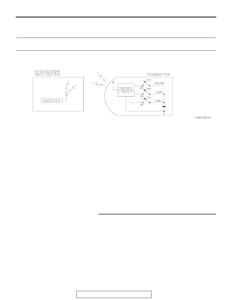
CIRCUIT OPERATION
The keyless entry receiver-ECU receives the 
lock/unlock signal from the transmitter.

.

TECHNICAL DESCRIPTION (COMMENT)
The cause may be a malfunction of the receiver and 
transmitter communication system.

.

TROUBLESHOOTING HINTS

• Malfunction of the keyless entry receiver-ECU

• Malfunction of the transmitter

DIAGNOSIS

Required Special Tools:

• MB991223: Harness Set

• MB991529: Diagnostic Trouble Code Check Harness

• MB991958: Scan Tool (MUT-III Sub Assembly)

• MB991824: Vehicle Communication Interface (V.C.I.)

• MB991827: MUT-III USB Cable

• MB991911: MUT-III Main Harness B

STEP 1. Select a tester.
Q: Do you use scan tool MB991958?

YES : Go to Step 2.
NO :  Go to Step 3.

AC004797

Receiver and Transmitter Communication Circuit

AB

KEYLESS ENTRY SYSTEM

TSB Revision

BODY

42-156

STEP 2. Check the input signal (by using the pulse check 
mode of the monitor) (by using MB991958).
Check input signals from the transmitter.

CAUTION

To prevent damage to scan tool MB991958, always turn the 
ignition switch to the "LOCK" (OFF) position before con-
necting or disconnecting scan tool MB991958.
(1) Connect scan tool MB991958 to the data link connector.
(2) Operate scan tool MB991958 as follows:

1. Select "SYSTEM SELECT."
2. Select "SWS."
3. Select "PULSE CHECK."

(3) Push the transmitter "LOCK" or "UNLOCK" switch.
(4) Check that scan tool MB991958 sounds
Q: When the transmitter "LOCK" or "UNLOCK" switch is 

turned ON, does scan tool MB991958 sound?
YES : 
Replace the keyless entry receiver-ECU. All the doors 

can be locked or unlocked by means of the 
transmitter. Go to Step 5.

NO :  Go to Step 4.

STEP 3. Check the keyless entry receiver-ECU input signal 
(by using a voltmeter).
(1) Use special tool MB991529 to connect a voltmeter between 

ground terminal 4 or 5 and the keyless entry receiver-ECU 
terminal 1 of the data link connector.

(2) If a voltmeter indicator deflects once when transmitter's 

lock/unlock switches are operated, the keyless entry 
receiver-ECU input signal for that switch circuit system is 
normal.

Q: Is the input signal of transmitter normal?

YES : Replace the keyless entry receiver-ECU. All the doors 

can be locked or unlocked by means of the 
transmitter. Go to Step 5.

NO :  Go to Step 4.

AK303629AB

MB991911

MB991827

MB991824 

16-PIN

AC004936

MB991529

GROUND TERMINAL

AB

RECEIVER TERMINAL

KEYLESS ENTRY SYSTEM

TSB Revision

BODY

42-157

STEP 4. Measure the voltage at transmitter battery.
(1) Remove the transmitter battery. (Refer to 

P.42-163

.)

(2) Measure the transmitter battery's voltage.

• Voltage should be approximately 2.5 − 3.2 volts (battery 

positive voltage).

Q: Is the measured voltage approximately 2.5 

 3.2 volts?

YES : Go to Step 6.
NO :  Replace transmitter battery (Refer to 

P.42-163

.), then 

go to Step 5.

STEP 5. Check the transmitter.
Use other transmitter to register the secret code. (Refer to 

P.42-163

.)

Q: Does the lock/unlock switch operate normally?

YES : Replace the transmitter. Then go to Step 6.
NO :  Replace the keyless entry receiver-ECU. Then go to 

Step 6.

STEP 6. Retest the system.
Q: Does the transmitter operate normally?

YES : The procedure is complete.
NO :  Return to Step 1.

INSPECTION PROCEDURE 2: The Secret Code cannot be Registered.

NOTE: If the transmitter battery has been changed 
(Refer to 

P.42-163

.) but the secret code cannot be 

registered, the keyless entry receiver-ECU may be 
faulty. Check the following circuits, replace the key-
less entry receiver-ECU if necessary.

.

CIRCUIT OPERATION

• Refer to GROUP 13A, Symptom procedure 

P.13A-716

.

.

TECHNICAL DESCRIPTION (COMMENT) 
The cause may be a malfunction of the keyless entry 
receiver-ECU or data link circuit.

.

TROUBLESHOOTING HINTS

• Malfunction of the keyless entry receiver-ECU

• Damaged harness wire or connector

.

Data Link Power Supply and Ground Circuit
Refer to GROUP 13A, Symptom procedure 

P.13A-716

.

AC004486

KEYLESS ENTRY SYSTEM

TSB Revision

BODY

42-158

INSPECTION PROCEDURE 3: The Dome Light, the Cargo Space Light and the Hazard Warning Lights 
do not Operate through the Answerback Function. (However, the Dome Light, the Cargo Space Light 
and the Hazard Warning Lights Operates Normally.)

.

CIRCUIT OPERATION
The keyless entry receiver-ECU sends a keyless 
entry system answerback signal to the ETACS-ECU.

.

TECHNICAL DESCRIPTION (COMMENT)
It is suspected that the keyless entry receiver-ECU 
does not send any signal to the ETACS-ECU, or the 
ETACS-ECU is defective. 

.

TROUBLESHOOTING HITS

• Malfunction of the keyless entry receiver-ECU

• Malfunction of the ETACS-ECU

• Damaged harness wires or connectors

AC004799AB

Answerback Circuit

AC004311BG

CONNECTOR: D-27

JUNCTION

BLOCK (REAR)

D-27 (B)

AC004329AK

CONNECTORS: E-25, E-42

E-25 (B)

E-42


Content   ..  473  474  475  476   ..