Mitsubishi Montero (2004+). Manual - part 957
 

  Index      Mitsubishi     Mitsubishi Montero - service repair manual 2004 year


Search            


Content   ..  955  956  957  958   ..


Mitsubishi Montero (2004+). Manual - part 957


TRANSFER DIAGNOSIS <ACTIVE TRAC AWD II>

TSB Revision

AUTOMATIC TRANSMISSION

23A-403

.

CIRCUIT OPERATION
When turning the ignition switch to "ON," the trans-
fer-ECU (terminal number 13) receives battery volt-
age from the ignition switch.

.

DTC SET CONDITIONS
When power supply voltage drops to 9.5 volts and 
less, the DTC 11 is set as low voltage. When power 
supply voltage rises to 18 volts and over, the DTC 12 
is set as high voltage.

.

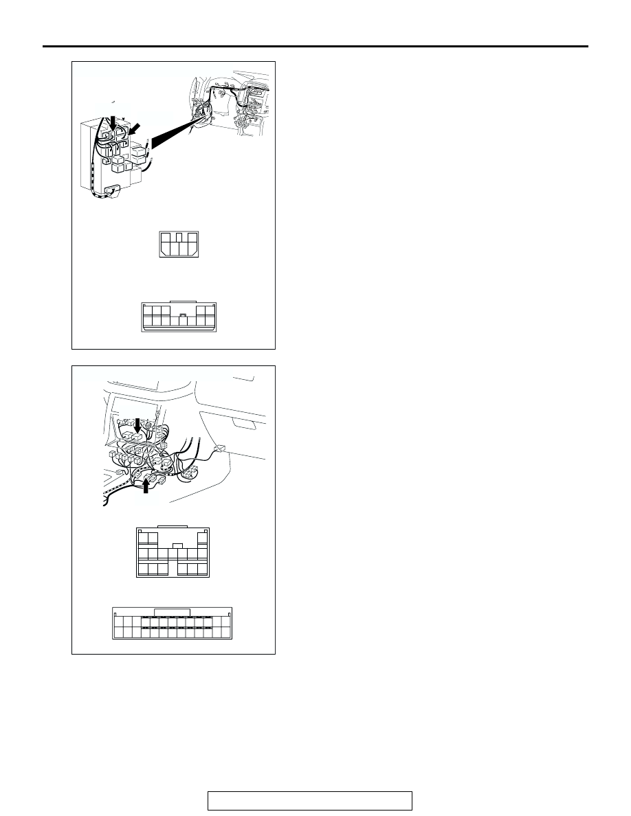
AC204191

CONNECTORS : D-208, D-210

D-208

D-208

D-210

D-210

AP

5 6

2

4

3

1

5

4

12 13

3

2

9

7 8

10

6

1

11

AC204194

CONNECTORS : E-11, E-109

E-109

E-109

E-11

E-11

AW

3

10

16

9

7 8

6

1

4

2

5

11

14

1213

15

11 12

25

24

13

26

9

22

7

6

20

19

8

21

10

23

5

4

17

2

1

15

14

3

16

18

TRANSFER DIAGNOSIS <ACTIVE TRAC AWD II>

TSB Revision

AUTOMATIC TRANSMISSION

23A-404

TROUBLESHOOTING HINTS (THE MOST LIKELY 
CAUSES FOR THIS CODE TO BE SET ARE:)

• Malfunction of the ignition switch

• Damaged harness, connector

• Malfunction of the transfer-ECU

DIAGNOSIS

Required Special Tool:

• MB991958: Scan Tool (MUT-III Sub Assembly)

• MB991824: V.C.I.

• MB991827: MUT-III USB Cable

• MB991911: MUT-III Main Harness B

STEP 1. Using scan tool MB991958, check data list item 09: 
Ignition switch power supply.

CAUTION

To prevent damage to scan tool MB991958, always turn the 
ignition switch to the "LOCK" (OFF) position before con-
necting or disconnecting scan tool MB991958.
(1) Connect scan tool MB991958 to the data link connector.
(2) Turn the ignition switch to the "ON" position.
(3) Set scan tool MB991958 to data reading mode.

• Item 09: Ignition Switch Power Supply.

• The voltage should equal battery positive voltage.

(4) Turn the ignition switch to the "LOCK" (OFF) position.
Q: Is the measured voltage equal battery positive voltage?

YES : It can be assumed that this malfunction is intermittent. 

Refer to GROUP 00, How to Use 
Troubleshooting/Inspection Service Points 

− How to 

Cope with Intermittent Malfunction 

P.00-6

.

NO :  Go to Step 2.

AC307591 AC

MB991911

MB991824

MB991827

AC307591

DATA LINK

CONNECTOR

TRANSFER DIAGNOSIS <ACTIVE TRAC AWD II>

TSB Revision

AUTOMATIC TRANSMISSION

23A-405

STEP 2. Measure the power supply voltage at transfer-ECU 
connector E-109 by backprobing.
(1) Do not disconnect connector E-109.
(2) Turn the ignition switch to the "ON" position.

(3) Measure the voltage between terminal 13 and ground by 

backprobing.

• The voltage should measure battery positive voltage.

(4) Turn the ignition switch to "LOCK" (OFF) position.
Q: Is the measured voltage battery positive voltage?

YES : Go to Step 5.
NO :  Go to Step 3.

AC204176

CONNECTOR : E-109

BB

11 12

25

24

13

26

9

22

7

6

20

19

8

21

10

23

5

4

17

2

1

15

14

3

16

18

AC204918

11 12

25

24

13

26

9

22

7

6

20

19

8

21

10

23

5

4

17

2

1

15

14

3

16

18

CA

E-109 HARNESS CONNECTOR : 
HARNESS SIDE

TRANSFER DIAGNOSIS <ACTIVE TRAC AWD II>

TSB Revision

AUTOMATIC TRANSMISSION

23A-406

STEP 3. Check joint connector D-01, junction block 
connector D-208, D-210, intermediate connector E-11 and 
transfer-ECU connector E-109 for loose, corroded or 
damaged terminals, or terminals pushed back in the 
connector.

AC204170

CONNECTOR : D-01

CD

9 10

8

6 7

31 32

30

29

18 19 20 21

5

4

2

1

3

27

26

24

23

25

12 13 14 15 16 17

28

11
22
33

AC204191

CONNECTORS : D-208, D-210

D-208

D-208

D-210

D-210

AP

5 6

2

4

3

1

5

4

12 13

3

2

9

7 8

10

6

1

11


Content   ..  955  956  957  958   ..