Mitsubishi Montero (2004+). Manual - part 942
 

  Index      Mitsubishi     Mitsubishi Montero - service repair manual 2004 year


Search            


Content   ..  940  941  942  943   ..


Mitsubishi Montero (2004+). Manual - part 942


AUTOMATIC TRANSMISSION DIAGNOSIS

TSB Revision

AUTOMATIC TRANSMISSION

23A-343

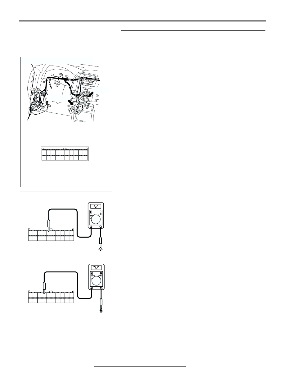
STEP 4. Measure the power supply voltage at A/C-ECU 
connector D-23 <Vehicles with full automatic A/C> or 
automatic compressor controller connector D-119 
<Vehicles with manual A/C> by backprobing.
(1) Do not disconnect connector D-23 <Vehicles with full 

automatic A/C> or D-119 <Vehicles with manual A/C>.

(2) Start the engine and run at idle.
(3) Operate the A/C.

(4) Measure the voltage between A/C-ECU connector D-23 

terminal 5 and ground by backprobing. <Vehicles with full 
automatic A/C>
Measure the voltage between automatic compressor 
controller connector D-119 terminal 4 and ground by 
backprobing. <Vehicles with manual A/C>

• The voltage should measure battery positive voltage.

(5) Turn the ignition switch to the "LOCK" (OFF) position.
Q: Is the measured voltage battery positive voltage?

YES : Go to Step 8.
NO :  Go to Step 5.

AC204188

CONNECTORS : D-23, D-119

D-23 (B)

D-23, D-119

D-119 (B)

BD

20

10

19

9

17

7

16

6

14

4

3

13

5

15

11

1 2

12

8

18

8

2

1

5

3 4

6 7

9 10

20

19

18

17

16

15

14

13

12

11

8

2

1

5

3 4

6 7

9 10

20

19

18

17

16

15

14

13

12

11

AC205399

D-23 HARNESS CONNECTOR : 
COMPONENT SIDE

<VEHICLES WITH FULL AUTOMATIC A/C>

<VEHICLES WITH MANUAL A/C>

D-119 HARNESS CONNECTOR : 
COMPONENT SIDE

AB

AUTOMATIC TRANSMISSION DIAGNOSIS

TSB Revision

AUTOMATIC TRANSMISSION

23A-344

STEP 5. Check intermediate connector D-28, A/C-ECU 
connector D-23 <Vehicles with full automatic A/C> and 
automatic compressor controller connector D-119 
<Vehicles with manual A/C> for loose, corroded or 
damaged terminals, or terminals pushed back in the 
connector.
Q: Are the connectors and terminals in good condition?

YES : Go to Step 6.
NO :  Repair or replace the damaged components. Refer to 

GROUP 00E, Harness Connector Inspection 

P.00E-2

.

AC204188

CONNECTORS : D-23, D-28, D-119

D-23 (B)

D-23, D-119

D-119 (B)

BE

D-28

D-28

20

10

19

9

17

7

16

6

14

4

3

13

5

15

11

1 2

12

8

18

2 3

27

32

28

33

16

15

4 5

19

18

29

17

34

7 8

35

22

21

9 10

30

36

31

37

25

24

23

6

20

1

14

26

11

13

12

38

AUTOMATIC TRANSMISSION DIAGNOSIS

TSB Revision

AUTOMATIC TRANSMISSION

23A-345

STEP 6. Check harness for short circuit to ground between 
dual pressure switch connector A-22 terminal 2 and 
A/C-ECU connector D-23 terminal 5 <Vehicles with full 
automatic A/C> or dual pressure switch connector A-22 
terminal 2 and automatic compressor controller connector 
D-119 terminal 4 <Vehicles with manual A/C>.
Q: Is the harness wire in good condition?

YES : Go to Step 7.
NO :  Repair or replace the harness wire.

AC204167

CONNECTOR : A-22

AV

A-22 (BR)

A-22

1 2

AC204188

CONNECTORS : D-23, D-119

D-23 (B)

D-23, D-119

D-119 (B)

BD

20

10

19

9

17

7

16

6

14

4

3

13

5

15

11

1 2

12

8

18

AUTOMATIC TRANSMISSION DIAGNOSIS

TSB Revision

AUTOMATIC TRANSMISSION

23A-346

STEP 7. Using scan tool MB991958, check data list item 65: 
Dual Pressure Switch.

CAUTION

To prevent damage to scan tool MB991958, always turn the 
ignition switch to the "LOCK" (OFF) position before con-
necting or disconnecting scan tool MB991958.
(1) Connect scan tool MB991958 to the data link connector.
(2) Start the engine and run at idle.
(3) Set scan tool MB991958 to data reading mode.

• Item 65: Dual Pressure Switch.

• When the A/C is in operation, scan tool MB991958 

display should be "ON."

• When the A/C is not in operation, scan tool 

MB991958 display should be "OFF."

(4) Turn the ignition switch to the "LOCK" (OFF) position.
Q: Is the switch operating properly?

YES : It can be assumed that this malfunction is intermittent. 

Refer to GROUP 00, How to Use 
Troubleshooting/Inspection Service Points 

− How to 

Cope with Intermittent Malfunction 

P.00-6

.

NO :  Check the air conditioning system. Refer to GROUP 

55, Troubleshooting Strategy 

P.55A-5

AC307591 AC

MB991911

MB991824

MB991827

AC307591

DATA LINK

CONNECTOR


Content   ..  940  941  942  943   ..