Mitsubishi Montero (2004+). Manual - part 924
 

  Index      Mitsubishi     Mitsubishi Montero - service repair manual 2004 year


Search            


Content   ..  922  923  924  925   ..


Mitsubishi Montero (2004+). Manual - part 924


AUTOMATIC TRANSMISSION DIAGNOSIS

TSB Revision

AUTOMATIC TRANSMISSION

23A-271

STEP 2. Using scan tool MB991958, check data list item 36: 
Torque Converter Clutch Solenoid Valve Duty%.
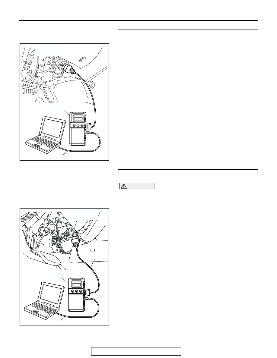
(1) Connect scan tool MB991958 to the data link connector.
(2) Turn the ignition switch to the "ON" position.
(3) Set scan tool MB991958 to the data reading mode.

• Item 36: Torque Converter Clutch Solenoid Valve 

Duty%.

• When driving at constant speed of 80 km/h (50 

mph), the display should be "70 

− 99.6%" (Gear 

range: 4th gear).

• When the accelerator pedal is released [at less than 

50 km/h (31 mph)], the display should be "70 

− 

99.6% 

→ 0%" (decreases gradually as the vehicle 

speed decreases) (Gear range: 4th gear).

(4) Turn the ignition switch to the "LOCK" (OFF) position.
Q: Is the solenoid valve operating properly?

YES : Go to Step 3.
NO :  Go to Step 5.

STEP 3. Using scan tool MB991958, check data list item 52: 
Torque Converter Clutch Amount of Slippage.

CAUTION

To prevent damage to scan tool MB991958, always turn the 
ignition switch to the "LOCK" (OFF) position before con-
necting or disconnecting scan tool MB991958.
(1) Connect scan tool MB991958 to the data link connector.
(2) Start the engine. (Warming up engine)
(3) Set scan tool MB991958 to the data reading mode.

• Item 52: Torque Converter Clutch Amount of Slippage.

• Driving at a constant speed of 80 km/h (50 mph), the 

display should be "

−10 to 10 r/min."

• If the accelerator pedal is released, the display on 

the scan tool changes (50 km/h (31 mph) and less).

(4) Turn the ignition switch to the "LOCK" (OFF) position.
Q: Is the clutch operating properly?

YES : Go to Step 4.
NO :  Go to Step 5.

AC305412

AB

MB991910

DATA LINK

CONNECTOR

MB991824

MB991827

AC307591 AC

MB991911

MB991824

MB991827

AC307591

DATA LINK

CONNECTOR

AUTOMATIC TRANSMISSION DIAGNOSIS

TSB Revision

AUTOMATIC TRANSMISSION

23A-272

STEP 4. Using scan tool MB991958, read the A/T 
diagnostic trouble code.

CAUTION

To prevent damage to scan tool MB991958, always turn the 
ignition switch to the "LOCK" (OFF) position before con-
necting or disconnecting scan tool MB991958.
(1) Connect scan tool MB991958 to the data link connector.
(2) Turn the ignition switch to the "ON" position.
(3) Check for A/T diagnostic trouble code.
(4) Turn the ignition switch to the "LOCK" (OFF) position.
Q: Is DTC 52 set?

YES : Replace the PCM.
NO :  The procedure is complete.

STEP 5. Check the hydraulic pressure (for torque 
converter).
Measure the hydraulic pressure for torque converter. Check if 
the hydraulic pressure is within the standard value. Refer to 

P.23A-26

, Hydraulic Pressure Test.

Q: Is the hydraulic pressure within the standard value?

YES : Go to Step 7.
NO :  Go to Step 6.

STEP 6. Adjust line pressure.
Adjust line pressure. Refer to 

P.23A-41

, Line Pressure Adjust-

ment. Then check the symptom.
Q: Is the symptom eliminated?

YES : The procedure is complete.
NO :  Go to Step 8.

STEP 7. Replace the PCM.
Q: Is the symptom eliminated?

YES : The procedure is complete.
NO :  Go to Step 8.

AC307591 AC

MB991911

MB991824

MB991827

AC307591

DATA LINK

CONNECTOR

AUTOMATIC TRANSMISSION DIAGNOSIS

TSB Revision

AUTOMATIC TRANSMISSION

23A-273

STEP 8. Replace the valve body.
(1) Replace the valve body. Refer to GROUP 23B, 

Transmission 

P.23B-14

.

(2) Test drive the vehicle.
(3) Check for A/T diagnostic trouble code.
Q: Is DTC 52 set?

YES : Replace the torque converter. Refer to 

P.23A-563

Transmission and Transfer Assembly.

NO :  The procedure is complete.

DTC 53 (P0742): Torque Converter Clutch is Stuck On

.

DESCRIPTIONS OF MONITOR METHODS
With PCM signal for no lock-up engagement, if vehi-
cle speed equals or exceeds specified value, accel-
erator is ON, and torque converter slip amount is 
below specified value, PCM judges that torque con-
verter clutch is stuck ON.

.

MONITOR EXECUTION
Continuous

.

MONITOR EXECUTION CONDITIONS (OTHER 
MONITOR AND SENSOR)

Other Monitor (There is no temporary DTC stored 

in memory for the item monitored below)

• DTC 21 (P0335): Crankshaft position sensor mal-

function

• DTC 22 (P0715): Input shaft speed sensor mal-

function

• DTC 23 (P0720): Output shaft speed sensor mal-

function

• DTC 52 (P0741): Torque converter clutch system 

malfunction (Stuck OFF)

• DTC 36 (P0743): Torque converter clutch sole-

noid malfunction

• P0122: Throttle position sensor (main) malfunc-

tion (Low input)

• P0123: Throttle position sensor (main) malfunc-

tion (High input)

• P0222: Throttle position sensor (sub) malfunction 

(Low input)

• P0223: Throttle position sensor (sub) malfunction 

(High input)

• P2135: Throttle position sensor (main and sub) 

range/performance problem

• P0638: Throttle actuator control motor circuit 

range/performance problem

• P0642: Throttle position sensor power supply

• P1601: Communication malfunction (Between 

PCM and throttle actuator control module)

• P0606: PCM main prosessor malfunction

• P2108: Throttle actuator control module proces-

sor malfunction

• P2100: Throttle actuator control motor circuit 

(Open)

• P2101: Throttle actuator control motor magneto 

malfunction

• P2102: Throttle actuator control motor circuit 

(Shorted low)

• P2103: Throttle actuator control motor circuit 

(Shorted high)

• P2121: Accelerator pedal position sensor (main) 

circuit range/performance problem

• P2122: Accelerator pedal position sensor (main) 

circuit low input

• P2123: Accelerator pedal position sensor (main) 

circuit high input

• P2126: Accelerator pedal position sensor (sub) 

circuit range/performance problem

• P2127: Accelerator pedal position sensor (sub) 

circuit low input

• P2128: Accelerator pedal position sensor (sub) 

circuit high input

• P2138: Accelerator pedal position sensor (main 

and sub) range/performance problem

Sensor (The sensor below is determined to be 

normal)

• Input shaft speed sensor

• Output shaft speed sensor

• Crankshaft position sensor

• Torque converter clutch solenoid

ACX02161AD

VALVE BODY ASSEMBLY

AUTOMATIC TRANSMISSION DIAGNOSIS

TSB Revision

AUTOMATIC TRANSMISSION

23A-274

• Throttle position sensor

• Accelerator pedal position sensor

.

LOGIC FLOW CHARTS (Monitor Sequence)

.

AC205239

START

END

Transmission range 
switch position is in 
D, 3, 2 or L range

TCC solenoid is in
OFF steady state

TCC in disengagement area

Timer start

TCC in disengagement area

Timer > 5 secs.

V

THROTTLE

 > 1.5 V

N

OPG-B

 > 1,000 r/min

N

E

 - 5 < N

IPG-A

 < N

E

 + 5

Continuous failure 
for 10 secs.

Good

Malfunction

Yes

No

Yes

No

Yes

No

Yes

No

Yes

No

Yes

No

Yes

No

Yes

No

Yes

No

N

E

 : 

Engine speed

N

OPG-B 

: Output speed

            (output shaft speed sensor)

N

IPG-A 

: Input speed

           (input shaft speed sensor)

V

THROTTLE

 : Throttle position sensor 

                  output voltage

AC

Transmission range 
switch position is in 
D range


Content   ..  922  923  924  925   ..