Mitsubishi Montero (2004+). Manual - part 831
INPUT SIGNAL PROCEDURES
TSB Revision
SIMPLIFIED WIRING SYSTEM (SWS)
54B-581
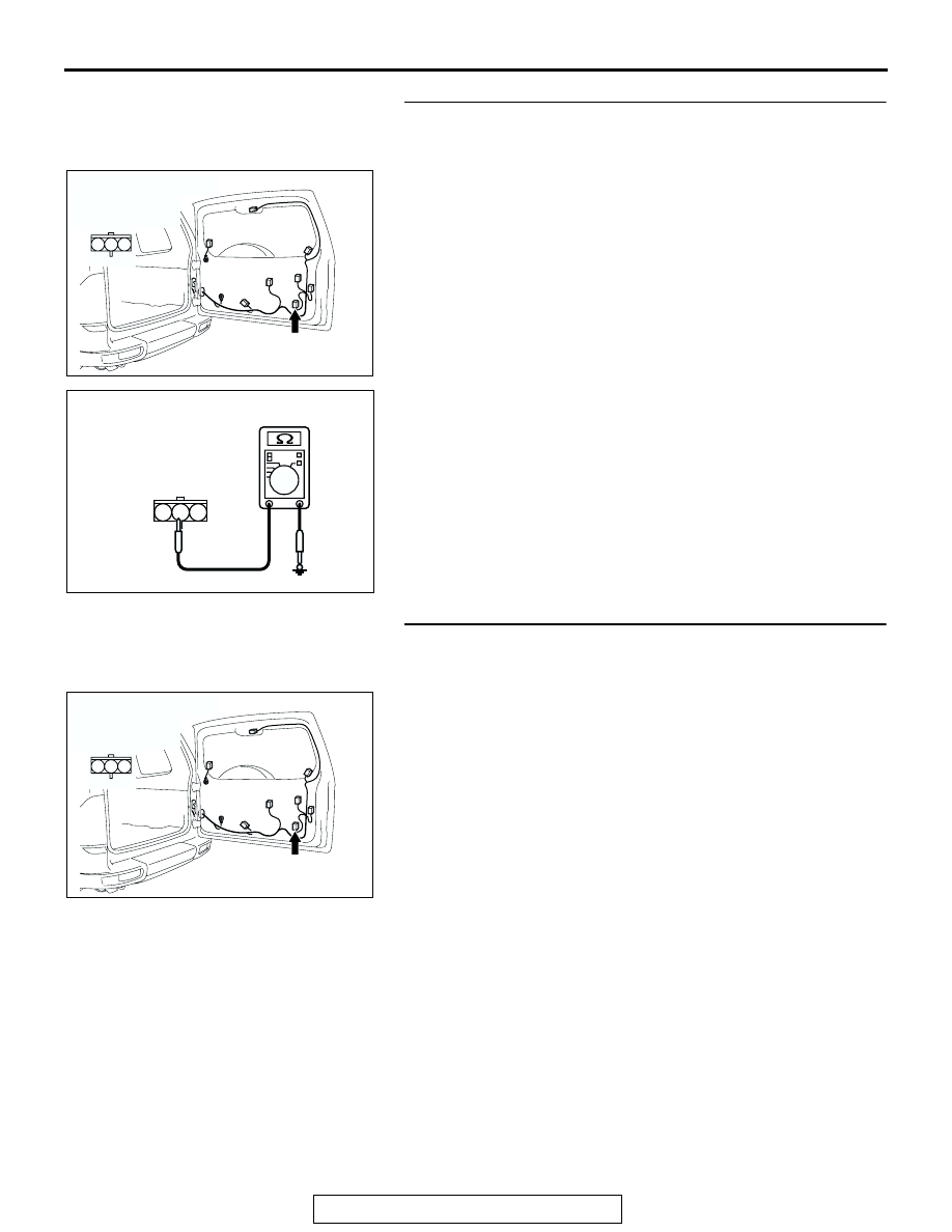
STEP 17. Check the ground circuit to the back door lock
key cylinder switch. Test at back door lock key cylinder
switch connector I-06.
(1) Disconnect back door lock key cylinder switch connector
I-06 measure the resistance available at the wiring harness
side of the connector.
(2) Measure the resistance value between terminal 2 and
ground.
• The resistance should equal 2 ohms or less.
Q: Is the measured resistance 2 ohms or less?
YES : Go to Step 19.
NO : Go to Step 18.
STEP 18. Check the wiring harness between back door
lock key cylinder switch connector I-06 (terminal 2) and
ground.
Q: Is the wiring harness between back door lock key
cylinder switch connector I-06 (terminal 2) and ground
in good condition?
YES : No action is necessary and testing is complete.
NO : The wiring harness may be damaged or the
connector(s) may have loose, corroded or damaged
terminals, or terminals pushed back in the connector.
Repair the wiring harness as necessary. If the
systems, which are described in "CIRCUIT
OPERATION", work normally, the input signal from
the back door lock key cylinder switch should be
normal.
AC204182
CONNECTOR : I-06
AD
HARNESS SIDE
2
3
1
I-06
AC204526
1
3 2
AB
CONNECTOR I-06
(HARNESS SIDE)
AC204182
CONNECTOR : I-06
AD
HARNESS SIDE
2
3
1
I-06