Mitsubishi Montero (2004+). Manual - part 784
 

  Index      Mitsubishi     Mitsubishi Montero - service repair manual 2004 year


Search            


Content   ..  782  783  784  785   ..


Mitsubishi Montero (2004+). Manual - part 784


SYMPTOM PROCEDURES

TSB Revision

SIMPLIFIED WIRING SYSTEM (SWS)

54B-393

STEP 20. Check the rear turn-signal light bulb (RH).
(1) Remove the rear turn-signal (RH) light bulb.
(2) Verify that the rear turn-signal light bulb (RH) is not 

damaged or burned out.

Q: Is the rear turn-signal (RH) light bulb in good condition?

YES : Go to Step 21.
NO :  Replace the rear turn-signal (RH) light bulb. Verify 

that the turn-signal lights illuminate normally.

STEP 21. Check rear combination light (RH) connector 
G-09 for loose, corroded or damaged terminals, or 
terminals pushed back in the connector.
Q: Is rear combination light (RH) connector G-09 in good 

condition?
YES : 
Go to Step 22.
NO :  Repair or replace the damaged component(s). Refer 

to GROUP 00E, Harness Connector Inspection 

P.00E-2

Verify that the turn-signal lights illuminate 

normally.

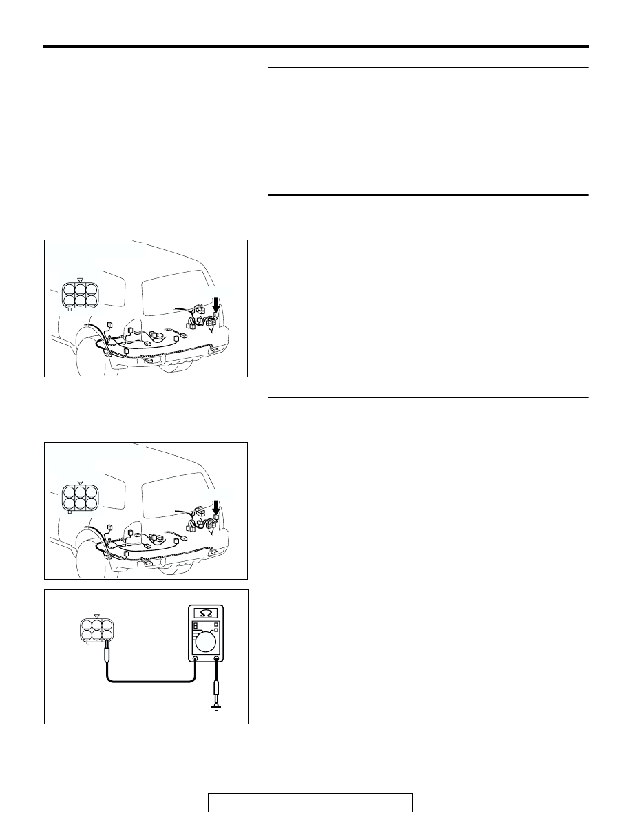
STEP 22. Check the ground circuit to the rear combination 
light (RH). Test at rear combination light (RH) connector 
G-09. 
(1) Disconnect rear combination light (RH) connector G-09 and 

measure the resistance available at the wiring harness side 
of the connector.

(2) Measure the resistance value between terminal 4 and 

ground.

• The resistance should equal 2 ohms or less.

Q: Is the measured resistance 2 ohms or less?

YES : Go to Step 24.
NO :  Go to Step 23.

AC204179

CONNECTOR : G-09

AC

HARNESS SIDE

G-09(B)

G-09(B)

1

4

2

3

5

6

AC204179

CONNECTOR : G-09

AC

HARNESS SIDE

G-09(B)

G-09(B)

1

4

2

3

5

6

AC100256

1

4

2

3

5

6

AC

CONNECTOR G-09
(HARNESS SIDE)

SYMPTOM PROCEDURES

TSB Revision

SIMPLIFIED WIRING SYSTEM (SWS)

54B-394

STEP 23. Check the wiring harness between rear 
combination light (RH) connector G-09 (terminal 4) and 
ground.
Q: Is the wiring harness between rear combination light 

(RH) connector G-09 (terminal 4) and ground in good 
condition?
YES : 
Replace the socket assembly. Verify that the 

turn-signal lights illuminate normally.

NO :  The wiring harness may be damaged or the 

connector(s) may have loose, corroded or damaged 
terminals, or terminals pushed back in the connector. 
Repair the wiring harness as necessary. Verify that 
the turn-signal lights illuminate normally.

STEP 24. Check ETACS-ECU connector D-222 for loose, 
corroded or damaged terminals, or terminals pushed back 
in the connector.
Q: Is ETACS-ECU connector D-222 in good condition?

YES : Go to Step 25.
NO :  Repair or replace the damaged component(s). Refer 

to GROUP 00E, Harness Connector Inspection 

P.00E-2

Verify that the turn-signal lights illuminate 

normally.

AC204179

CONNECTOR : G-09

AC

HARNESS SIDE

G-09(B)

G-09(B)

1

4

2

3

5

6

AC204174

CONNECTOR : D-222

AB

1

2

3

5

6

4

9 8

121110

13

15 14

16

17

7

19

20

18

JUNCTION BLOCK SIDE

D-222

SYMPTOM PROCEDURES

TSB Revision

SIMPLIFIED WIRING SYSTEM (SWS)

54B-395

STEP 25. Check the wiring harness between rear 
combination light (RH) connector G-09 (terminal 5) and 
ETACS-ECU connector D-222 (terminal 14).

NOTE: Also check junction block connector D-217 and inter-
mediate connector D-111 for loose, corroded, or damaged ter-
minals, or terminals pushed back in the connector. If junction 
block connector D-217 or intermediate connector D-111 is dam-
aged, repair or replace the damaged component(s) as 
described in GROUP 00E, Harness Connector Inspection 

P.00E-2

.

Q: Is the wiring harness between rear combination light 

(RH) connector G-09 (terminal 5) and ETACS-ECU 
connector D-222 (terminal 14) in good condition?
YES : 
Replace the socket assembly. Verify that the 

turn-signal lights illuminate normally.

NO :  The wiring harness may be damaged or the 

connector(s) may have loose, corroded or damaged 
terminals, or terminals pushed back in the connector. 
Repair the wiring harness as necessary. Verify that 
the turn-signal lights illuminate normally.

AC204174

CONNECTOR : D-222

AB

1

2

3

5

6

4

9 8

121110

13

15 14

16

17

7

19

20

18

JUNCTION BLOCK SIDE

D-222

AC204179

CONNECTOR : G-09

AC

HARNESS SIDE

G-09(B)

G-09(B)

1

4

2

3

5

6

AC204171

CONNECTOR : D-111

BH

9

8

6 7

5

3 4

20

32

21

33

43

17 18

30

41

16

29

28

39 40

13

25

12

24

35 36

14

26

37

15

27

38

19

31

42

1

10

22

2

11

23

34

AC204173

CONNECTOR : D-217

AG

HARNESS SIDE

8

1

11 10

3

4

12

9

2

13

14

6 5

15

7

D-217

SYMPTOM PROCEDURES

TSB Revision

SIMPLIFIED WIRING SYSTEM (SWS)

54B-396

STEP 26. Check combination meter connector D-03 and 
ETACS-ECU connector D-222 for loose, corroded or 
damaged terminals, or terminals pushed back in the 
connector.
Q: Are combination meter connector D-03 and ETACS-ECU 

connector D-222 in good condition?
YES : 
Go to Step 27.
NO :  Repair or replace the damaged component(s). Refer 

to GROUP 00E, Harness Connector Inspection 

P.00E-2

Verify that the turn-signal lights illuminate 

normally.

STEP 27. Check the wiring harness between combination 
meter connector D-03 (terminal 60) and ETACS-ECU 
connector D-222 (terminal 15).

AC204170

CONNECTOR : D-03

AC

D-03(GR)

HARNESS 
SIDE

51

52

61 60

53

54

56

57

55

63

66 65 64

59

62

58

67

D-03(GR)

AC204174

CONNECTOR : D-222

AB

1

2

3

5

6

4

9 8

121110

13

15 14

16

17

7

19

20

18

JUNCTION BLOCK SIDE

D-222

AC204170

CONNECTOR : D-03

AC

D-03(GR)

HARNESS 
SIDE

51

52

61 60

53

54

56

57

55

63

66 65 64

59

62

58

67

D-03(GR)

AC204174

CONNECTOR : D-222

AB

1

2

3

5

6

4

9 8

121110

13

15 14

16

17

7

19

20

18

JUNCTION BLOCK SIDE

D-222


Content   ..  782  783  784  785   ..