Mitsubishi Montero (2004+). Manual - part 728
 

  Index      Mitsubishi     Mitsubishi Montero - service repair manual 2004 year


Search            


Content   ..  726  727  728  729   ..


Mitsubishi Montero (2004+). Manual - part 728


SYMPTOM PROCEDURES

TSB Revision

SIMPLIFIED WIRING SYSTEM (SWS)

54B-169

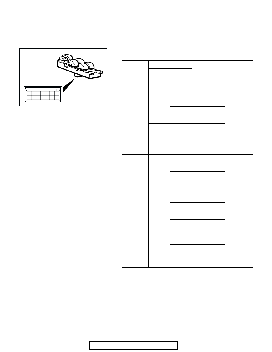
STEP 2. Check each switch on the power window main 
switch for continuity.
(1) Remove the power window main switch. Refer to 

P.42-31

.

(2) Check continuity when each switch on the power window 

main switch is operated to "UP" or "DOWN" position.

Q: Is the power window main switch normal?

YES : Go to Step 3.
NO :  Replace the power window main switch. When the 

power window sub-switch is operated, the power 
windows should open or close normally.

SWITCHES 
TO BE 
CHECKED

SWITCH POSITION TESTER 

CONNECTION

SPECIFIED 
CONDITION

Power 
window 
lock 
switch

Power 
window 
switches 
to be 
checked

Front 
power 
window 
(RH)

Lock

UP

− 14

Less than 2 
ohms

OFF

− 14

DOWN

− 5

Unlock

UP

− 3, 5 − 14

OFF

− 3, 1 − 14,

− 14

DOWN

− 5, 3 − 14

Rear 
power 
window 
(LH)

Lock

UP

− 13

Less than 2 
ohms

OFF

− 13

DOWN

− 6

Unlock

UP

− 6, 5 − 13

OFF

− 6, 3 − 13,

− 13

DOWN

− 13, 5 − 6

Rear 
power 
window 
(RH)

Lock

UP

− 5

Less than 2 
ohms

OFF

− 9

DOWN

− 9

Unlock

UP

− 5, 3 − 9

OFF

− 3, 2 − 9,

− 9

DOWN

− 3, 5 − 9

7

6

5

4

3

2

1

14

13

12

11

10

9

8

ACX02412 AC

SYMPTOM PROCEDURES

TSB Revision

SIMPLIFIED WIRING SYSTEM (SWS)

54B-170

STEP 3. Check the power window lock switch.
Q: Is the power window lock switch at the "UNLOCK" 

position?
YES : 
Go to Step 4.
NO :  Operate the power window lock switch to the 

"UNLOCK" position. When the power window 
sub-switch is operated, the power windows should 
open or close normally.

STEP 4. Check which door window is not opened or closed
Q: Which door window is not opened or closed?

 Front passenger's side : Go to Step 5.
 Rear passenger (LH) : Go to Step 18.
 Rear passenger (RH) : Go to Step 31.

STEP 5. Check front power window sub-switch (RH) 
connector H-16 for loose, corroded or damaged terminals, 
or terminals pushed back in the connector.
Q: Is front power window sub-switch (RH) connector H-16 

in good condition?
YES : 
Go to Step 6.
NO :  Repair or replace the damaged component(s). Refer 

to GROUP 00E, Harness Connector Inspection 

P.00E-2

. Verify that the front power window 

sub-switch (RH) should now work normally.

STEP 6. Check the front power window sub-switch (RH) for 
continuity.
(1) Remove the front power window sub-switch (RH). Refer to 

GROUP 42, Door-Door Trim and Waterproof Film 

P.42-31

.

(2) Check continuity when the front power window sub-switch 

(RH) is operated to "UP" or "DOWN" position.

Q: Is the front power window sub-switch (RH) normal?

YES : Go to Step 7.
NO :  Replace the front power window sub-switch (RH). 

Verify that the front power window sub-switch (RH) 
should now work normally.

AC000238

CONNECTOR: H-16

H-16

AF

H-16
(HARNESS SIDE)

SWITCH 
POSITION

TESTER 
CONNECTION

SPECIFIED 
CONDITION

UP

− 8, 6 − 10

Less than 2 ohms

OFF

− 8, 6 − 10

DOWN

− 8, 5 − 6

5

4

3

2

1

10

9

8

7

6

ACX02413AD

SYMPTOM PROCEDURES

TSB Revision

SIMPLIFIED WIRING SYSTEM (SWS)

54B-171

STEP 7. Check front power window motor (RH) connector 
H-17 for loose, corroded or damaged terminals, or 
terminals pushed back in the connector.
Q: Is front power window motor (RH) connector H-17 in 

good condition?
YES : 
Go to Step 8.
NO :  Repair or replace the damaged component(s). Refer 

to GROUP 00E, Harness Connector Inspection 

P.00E-2

. Verify that the front power window 

sub-switch (RH) should now work normally.

STEP 8. Check the front power window motor (RH).
(1) Remove the front power regulator assembly (RH). Refer to 

GROUP 42, Door-Door Glass and Regulator 

P.42-38

.

(2) Connect a battery to the motor terminal, and check that the 

motor runs freely.

Q: Is the front power window motor (RH) normal?

YES : Go to Step 9.
NO :  Replace the front power regulator assembly (RH). 

Verify that the front power window sub-switch (RH) 
should now work normally.

AC000238

CONNECTOR: H-17

AN

HARNESS
SIDE

PSSENGER'S DOOR

BATTERY CONNECTION

SLIDER POSITION

• Connect terminal 2 to the 

negative battery terminal

• Connect terminal 6 to the 

positive battery terminal

The slider moves up

• Connect terminal 2 to the 

positive battery terminal

• Connect terminal 6 to the 

negative battery terminal

The slider moves down

AC309019

1 2

SLIDER

AB

SYMPTOM PROCEDURES

TSB Revision

SIMPLIFIED WIRING SYSTEM (SWS)

54B-172

STEP 9. Check at front power window sub-switch 
connector H-16 in order to check the power window relay 
circuit of the power supply to the front power window 
sub-switch (RH).
(1) Disconnect front power window sub-switch (RH) connector 

H-16, and measure at the harness side.

(2) Measure the voltage between terminal 5 and ground.

• The voltage should measure approximately 12 volts 

(battery positive voltage).

Q: Is the measured voltage approximately 12 volts (battery 

positive voltage)?
YES : 
Go to Step 12.
NO :  Go to Step 10.

STEP 10. Check power window relay connector D-219 for 
loose, corroded or damaged terminals, or terminals 
pushed back in the connector.
Q: Is power window relay connector D-219 in good 

condition?
YES : 
Go to Step 11.
NO :  Repair or replace the damaged component(s). Refer 

to GROUP 00E, Harness Connector Inspection 

P.00E-2

. Verify that the front power window 

sub-switch (RH) should now work normally.

AC000238

CONNECTOR: H-16

H-16

AF

H-16
(HARNESS SIDE)

AC204312

1

2

3

4

5

6

7

8

9

10

AB

CONNECTOR H-16
(HARNESS SIDE)

AC203850AB

CONNECTOR: D-219

JUNCTION BLOCK 
(FRONT VIEW)

D-219

1

2

3

4

5

JUNCTION 
BLOCK SIDE

D-219


Content   ..  726  727  728  729   ..