Mitsubishi Montero (2004+). Manual - part 576
 

  Index      Mitsubishi     Mitsubishi Montero - service repair manual 2004 year


Search            


Content   ..  574  575  576  577   ..


Mitsubishi Montero (2004+). Manual - part 576


RV METER

TSB Revision

CHASSIS ELECTRICAL

54A-273

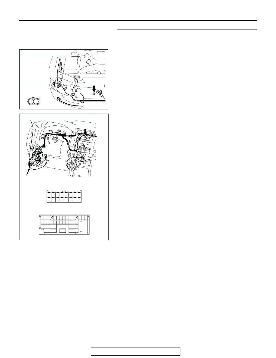
STEP 8. Check the harness wires between RV meter 
connector D-07 (terminal 23 and 31) and ambient air 
temperature sensor connector A-29 (terminal 1 and 2).

NOTE: After inspecting intermediate connector D-28 inspect 
the wires. If intermediate connector D-28 is damaged, repair or 
replace it. Refer to GROUP 00E, Harness Connector Inspec-
tion 

P.00E-2

.

Q: Are harness wires between RV meter connector D-07 

(terminal 23 and 31) and ambient air temperature sensor 
connector A-29 (terminal 1 and 2) in good condition?
YES : 
Go to Step 9.
NO :  Repair or replace them. Refer to GROUP 00E, 

Harness Connector Inspection 

P.00E-2

.

AC204166

CONNECTOR : A-29

AP

A-29(B)

A-29(B)

1

2

HARNESS 
SIDE

AC204188

CONNECTORS: D-07, D-28

BV

D-28

D-28

2 3

27

32

28

33

16

15

4 5

19

18

29

17

34

7 8

35

22

21

9 10

30

36

31

37

25

24

23

6

20

1

14

26

11

13

12

38

HARNESS SIDE

D-07(B)

D-07(B)

22

23

30

31

25

26

33

34

32

24

28

3635

27

29

21

RV METER

TSB Revision

CHASSIS ELECTRICAL

54A-274

STEP 9. Recheck for malfunction.
Q: Is a malfunction eliminated?

YES : If no malfunctions are not found in all steps, an 

intermittent malfunction is suspected. Refer to 
GROUP 00, How to Use Troubleshooting/Inspection 
Service Points 

− How to Cope with Intermittent 

Malfunction 

P.00-6

.

NO :  Replace the RV meter.

INSPECTION PROCEDURE 5: The Compass does not Indicate Normally. 

.

TECHNICAL DESCRIPTION (COMMENT)
The geomagnetism sensor integrated in the RV 
meter is abnormal, or it is seemed that the indication 
is affected by some nearby magnetized matter. 

.

TROUBLESHOOTING HINTS
Malfunction of the RV meter

.

DIAGNOSIS

STEP 1. Check the geomagnetism sensor mode in service 
mode. 
(1) When the adjusting switch is continuously pressed for more 

than five seconds, the reception sound (pip sound) is heard 
and at the same time the service function is activated to 
display the service mode screen. 

(2) Press the adjusting switch with the ignition switch at the 

"LOCK" (OFF) position. Then while keeping the switch on 
the pressed condition, turn the ignition switch to "ACC" 
position. 

(3) Check the geomagnetism sensor at the geomagnetism 

sensor mode (Refer to 

P.54A-284

.)

Q: Isn't there any abnormality on the geomagnetism 

sensor? 
YES : 
There is no action to be taken.
NO :  Step 2.

STEP 2.Check of own vehicle position.
Q: Is the geomagnetism stable at the place? 

YES : Go to Step 4.
NO :  Go to Step 3.

STEP 3. Move the vehicle to the geomagnetically stable 
location to re-check the geomagnetism.
Q: Isn't there any abnormality at the geomagnetism sensor 

mode? 
YES : 
There is no action to be taken.
NO :  Step 4.

RV METER

TSB Revision

CHASSIS ELECTRICAL

54A-275

STEP 4. Check of RV meter for magnetization. 
Q: Does the indication return to normal when the carrier 

antenna that is mounted on the body by a magnet, a 
magnet or metal existing nearby the RV meter is 
removed? 
YES : 
There is no action to be taken.
NO :  Replace the RV meter.

STEP 5. Recheck for malfunction.
Q: Is a malfunction eliminated?

YES : If no malfunctions are not found in all steps, an 

intermittent malfunction is suspected. Refer to 
GROUP 00,How to Use Troubleshooting/Inspection 
Service Points-How to Cope with Intermittent 
Malfunction 

P.00-6

.

NO :  Replace the RV meter.

RV METER

TSB Revision

CHASSIS ELECTRICAL

54A-276

INSPECTION PROCEDURE 6: The Air-Conditioner Information is not Displayed. 

.

CIRCUIT OPERATION
The RV meter receives operation picture image 
(M-BUS communication line) from the A/C-ECU and 
displays it. The RV meter receives operation picture 
image (M-BUS communication line) from the 
A/C-ECU and displays it. 

.

AMBIENT AIR
TEMPERATURE
SENSOR

RV METER

COMMUNICATION CIRCUIT

A/C-ECU

SIGNAL INPUT
CIRCUIT

A/C-ECU Circuit

AC204170

CONNECTORS : D-08, D-23

DM

D-08(B)

D-23(B)


Content   ..  574  575  576  577   ..