Mitsubishi Montero (2004+). Manual - part 562
 

  Index      Mitsubishi     Mitsubishi Montero - service repair manual 2004 year


Search            


Content   ..  560  561  562  563   ..


Mitsubishi Montero (2004+). Manual - part 562


VIDEO ENTERTAINMENT SYSTEM (VES)

TSB Revision

CHASSIS ELECTRICAL

54A-217

STEP 2. Check the rear display connector F-32 and video 
controller unit connector F-35 for loose, corroded or 
damaged terminals, or terminals pushed back in the 
connector.

Q: Is the rear display connector F-32 and video controller 

unit connector F-35 in good condition?
YES : 
Go to Step 3.
NO :  Repair or replace the component(s). Refer to GROUP 

00E, Harness Connector Inspection 

P.00E-2

. The 

remote controller works normally.

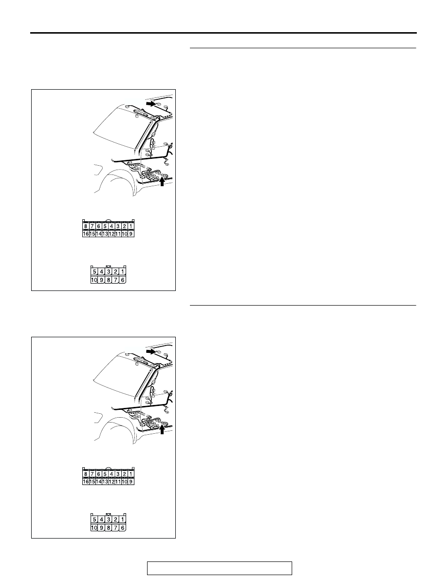
STEP 3. Check the wiring harness between rear display 
connector F-32 (terminal 7) and video controller unit 
connector F-35 (terminal 30).

AC309224

AB

CONNECTOR: F-32, F-35

HARNESS SIDE

F-32 (B)

F-32

F-35

HARNESS SIDE

F-35

AC309224

AB

CONNECTOR: F-32, F-35

HARNESS SIDE

F-32 (B)

F-32

F-35

HARNESS SIDE

F-35

VIDEO ENTERTAINMENT SYSTEM (VES)

TSB Revision

CHASSIS ELECTRICAL

54A-218

NOTE: Also check intermediate connector D-34 for loose, cor-
roded, or damaged terminals, or terminals pushed back in the 
connector. If intermediate connector D-34 is damaged, repair or 
replace. Refer to GROUP 00E, Harness Connector Inspection 

P.00E-2

.

Q: Is the wiring harness between rear display connector 

F-32 (terminal 7) and video controller unit connector 
F-35 (terminal 30) in good condition?
YES : 
Go to Step 4.
NO :  Repair the wiring harness. The remote controller 

works normally.

STEP 4. Substitute the remote controller, and retest the 
system.

Confirm that the remote controller functions correctly after it is 
substituted.
Q: Is the check result normal?

YES : Replace the remote controller.
NO :  Go to step 5.

STEP 5. Substitute the video controller unit, and retest the 
system.

Confirm that the remote controller functions correctly after the 
video controller unit is substituted.
Q: Is the check result normal?

YES : Replace the video controller unit.
NO :  Go to step 6.

STEP 6. Substitute the rear display, and retest the system.

Confirm that the remote controller functions correctly after the 
rear display is substituted.
Q: Is the check result normal?

YES : Replace the rear display.
NO :  Go to step 7.

STEP 7. Retest the system.
Q: Is the check result normal?

YES : The procedure is complete (If no malfunctions are 

found in all steps, an intermittent malfunction is 
suspected. Refer to GROUP 00, How to Use 
Troubleshooting/Inspection Service Point-How to 
Cope with Intermittent Malfunction 

P.00-6

).

NO :  Go to Step 1.

AC309207

AD

CONNECTOR: D-34

HARNESS SIDE

4

11

1

8 9

2

10

3

5

1213

6

14

7

VIDEO ENTERTAINMENT SYSTEM (VES)

TSB Revision

CHASSIS ELECTRICAL

54A-219

INSPECTION PROCEDURE 3: The image is unstable. The image color is abnormal.

.

CIRCUIT OPERATION
 Refer to 

P.54A-196

.

.

TECHNICAL DESCRIPTION (COMMENT)
The ground circuit, the battery circuit, the ignition 
switch (ACC) circuit is suspected to be open or 
defective.

.

TROUBLESHOOTING HINTS

• Malfunction of the video controller unit

• Malfunction of the rear display

• Damaged wiring harness and connectors

.

DIAGNOSIS 

Required Special Tool:

• MB991223: Harness Set

STEP 1. Check the rear display connector F-32 and video 
controller unit connector F-35 for loose, corroded or 
damaged terminals, or terminals pushed back in the 
connector.

Q: Is the rear display connector F-32 and video controller 

unit connector F-35 in good condition?
YES : 
Go to Step 2.
NO :  Repair or replace the component(s). Refer to GROUP 

00E, Harness Connector Inspection 

P.00E-2

. The 

rear display works normally.

AC309224

AB

CONNECTOR: F-32, F-35

HARNESS SIDE

F-32 (B)

F-32

F-35

HARNESS SIDE

F-35

VIDEO ENTERTAINMENT SYSTEM (VES)

TSB Revision

CHASSIS ELECTRICAL

54A-220

STEP 2. Check the wiring harness between rear display 
connector F-32 (terminal 1, 16, 15 and 7) and video 
controller unit connector F-35 (terminal 25, 23, 21 and 30).

NOTE: Also check intermediate connector D-34 for loose, cor-
roded, or damaged terminals, or terminals pushed back in the 
connector. If intermediate connector D-34 is damaged, repair or 
replace. Refer to GROUP 00E, Harness Connector Inspection 

P.00E-2

.

Q: Is the wiring harness between rear display connector 

F-32 (terminal 1, 16, 15 and 7) and video controller unit 
connector F-35 (terminal 25, 23, 21 and 30) in good 
condition?
YES : 
Go to Step 3.
NO :  Repair the wiring harness. The remote controller 

works normally.

STEP 3. Substitute the video controller unit, and retest the 
system.

Confirm that image is displayed normally after the video con-
troller unit is substituted.
Q: Is the check result normal?

YES : Replace the video controller unit.
NO :  Replace the rear display.

AC309224

AB

CONNECTOR: F-32, F-35

HARNESS SIDE

F-32 (B)

F-32

F-35

HARNESS SIDE

F-35

AC309207

AD

CONNECTOR: D-34

HARNESS SIDE

4

11

1

8 9

2

10

3

5

1213

6

14

7


Content   ..  560  561  562  563   ..