Mitsubishi Montero (2004+). Manual - part 453
 

  Index      Mitsubishi     Mitsubishi Montero - service repair manual 2004 year


Search            


Content   ..  451  452  453  454   ..


Mitsubishi Montero (2004+). Manual - part 453


ON-VEHICLE SERVICE

TSB Revision

FRONT AXLE

26-17

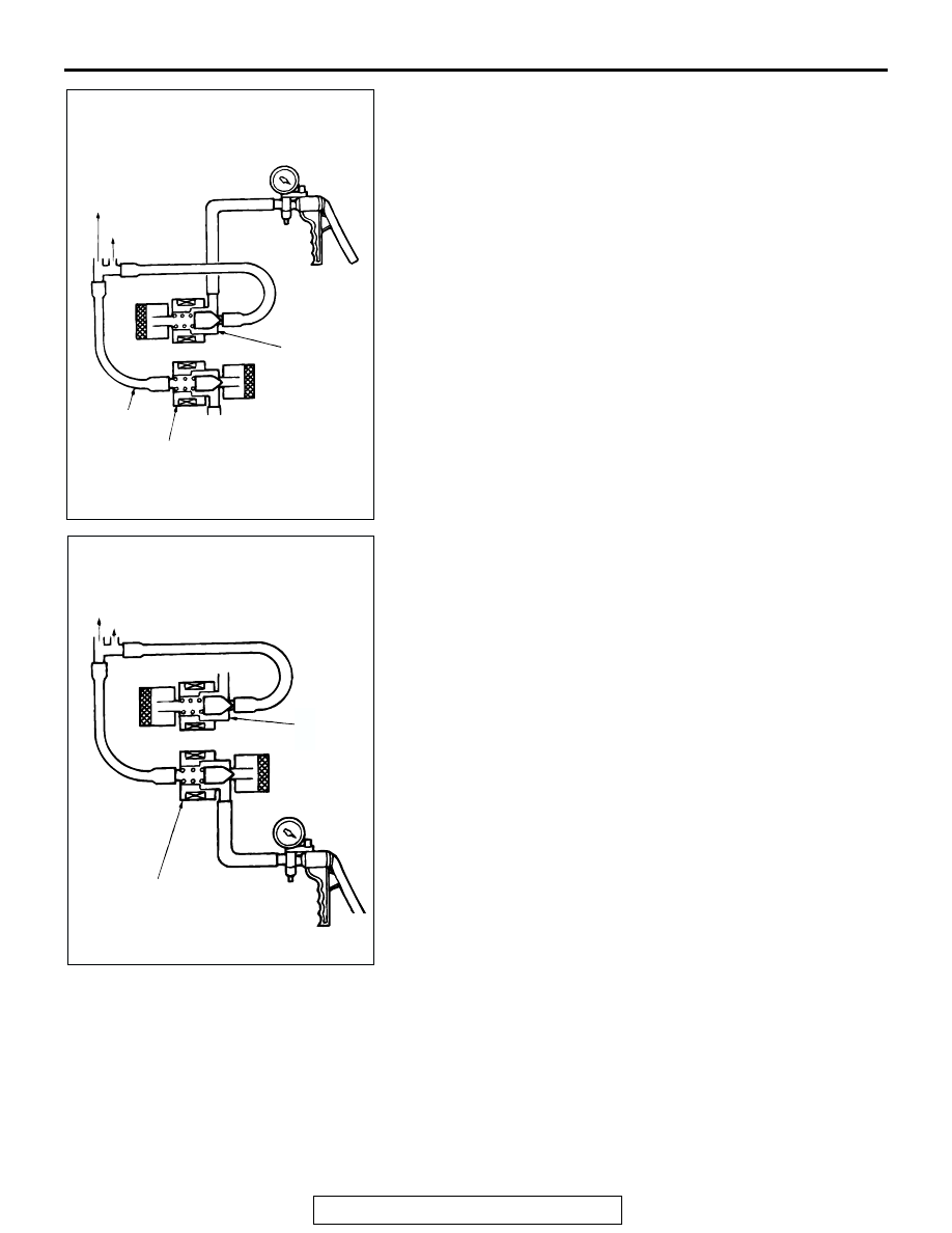
3. Connect a hand vacuum pump to solenoid valve A and carry 

out the following inspections.

(1) Even if the hand pump is operated with no other 

operation, no negative pressure develops.

(2) Negative pressure does not develop when battery 

voltage is applied to solenoid valve A. Negative pressure 
is maintained when the vacuum hose of solenoid valve B 
is blocked by bending.

(3) When battery voltage is applied to solenoids A and B, 

negative pressure is maintained.

4. Connect the hand vacuum pump to solenoid valve B. Apply 

negative pressure and carry out the following inspections.

(1) With no change, negative pressure is maintained.
(2) When battery voltage is applied to solenoid valve B, the 

vacuum shuts off.

(3) When battery voltage is applied to solenoid valve A, the 

vacuum shuts off.

5. Measure the resistance of the solenoid valves.

Standard value: 36 

 46  [at 20°C (68°F)]

ACX00969 AB

CHECK VALVE

VACUUME 
TANK

SOLENOID
VALVE A

SOLENOID
VALVE B

VACCUM
HOSE

ACX00970 AB

CHECK 
VALVE

VACUUME TANK

SOLENOID
VALVE B

SOLENOID
VALVE A

HUB AND KNUCKLE ASSEMBLY

TSB Revision

FRONT AXLE

26-18

HUB AND KNUCKLE ASSEMBLY

REMOVAL AND INSTALLATION

M1261003000071

Required Special Tools:

• MB990326: Preload Socket 

• MB990767: Front Hub and Flange Yoke Holder

• MB990998: Front Hub Remover and Installer 

• MB991897: Ball Joint Remover 

Post-installation Operation
Check the dust cover  for crack or damage by pushing it with 
your finger.

ACX00971 AC

39 

± 4 N

·

m

29 

± 3 ft-lb

147 

± 29 N

·

m

109 

± 21 ft-lb

8.9 

± 1.9 N

·

m

79 

± 17 in-lb

5.0 

± 1.0 N

·

m

44 

± 9 in-lb

200 

± 10 N

·

m

148 

± 7 ft-lb

74 

± 14 N

·

m

55 

± 3 ft-lb

113 

± 10 N

·

m

83 

± 7 ft-lb

9

11

5

10

13

8

7

3

2

1

6

4

12

N

N


REMOVAL 

STEPS 


1. HUB 

CAP

<<A>> >>D<<

2. CASTLE 

NUT


>>D<<

3. WASHER


4.  BRAKE HOSE AND VEHICLE 

SPEED SENSOR CLAMP 
BRACKET


5.  WHEEL SPEED SENSOR


6.  DISC BRAKE ASSEMBLY


7. BRAKE 

DISC


8. DUST 

COVER

<<B>> >>C<<

9.  TIE ROD END, HUB AND 

KNUCKLE ASSEMBLY 
CONNECTION

<<B>> >>B<<

10.  UPPER ARM, HUB AND KNUCKLE 

ASSEMBLY CONNECTION

<<B>> >>A<<

11.  LOWER ARM, HUB AND KNUCKLE 

ASSEMBLY CONNECTION


12. ROTOR PROTECTOR


13.  HUB AND KNUCKLE ASSEMBLY


REMOVAL STEPS  (Continued)

HUB AND KNUCKLE ASSEMBLY

TSB Revision

FRONT AXLE

26-19

REMOVAL SERVICE POINTS

.

<<A>> CASTLE NUT REMOVAL

CAUTION

Do not apply pressure to the wheel bearing by the vehicle 
weight to avoid possible damage when the castle nut is 
loosened. 
Use special tool MB990767 to fix hub and remove the drive 
shaft nut.

.

<<B>> TIE ROD END/UPPER ARM/LOWER ARM 
DISCONNECTION

CAUTION

• Do not remove the nut from ball joint. Loosen it and use 

special tool to avoid possible damage to ball joint 
threads.

• Hang special tool with cord to prevent it from falling. 

1. Install special tool MB991897 as shown in the figure.

2. Turn the bolt and knob as necessary to make the jaws of 

special tool MB991897 parallel, tighten the bolt by hand and 
confirm that the jaws are still parallel.
NOTE: When adjusting the jaws in parallel, make sure the 
knob is in the position shown in the figure.

3. Tighten the bolt with a wrench to disconnect the tie rod end.

INSTALLATION SERVICE POINTS

.

>>A<< LOWER ARM, HUB AND KNUCKLE ASSEMBLY 
CONNECTION
If the lower arm ball joint is disengaged from the knuckle, 
always renew the lower arm ball joint dust cover and retainer. 
(Refer to GROUP 33A-Lower Arm

P.33A-15

.)

.

ACX00972 AB

MB990767

AC106820 AB

CORD

BOLT

MB991897

NUT

BALL JOINT

AC106821

KNOB

PARALLEL

BOLT

CORRECT

WRONG

AC

HUB AND KNUCKLE ASSEMBLY

TSB Revision

FRONT AXLE

26-20

>>B<< UPPER ARM, HUB AND KNUCKLE ASSEMBLY 
CONNECTION
If the upper arm ball joint is disengaged from the knuckle, 
always renew the upper arm ball joint dust cover and retainer. 
(Refer to GROUP 33A-Upper Arm

P.33A-8

.)

.

>>C<< TIE ROD END, HUB AND KNUCKLE ASSEMBLY 
CONNECTION
If the tie rod end ball joint is disengaged from the knuckle, 
always renew the tie rod end ball joint dust cover and retainer 
by following the procedure below.
1. Unclip the spring ring to removed the dust cover.

CAUTION

Be careful not to damage the ball joint stud.
2. Use a flat-tipped screwdriver to remove the retainer.

3. Apply multi-purpose grease to the new retainer, and 

assemble it to the new dust cover.

4. Fill multi-purpose grease inside the dust cover as shown.

Amount to use: 4 

± 1 g (0.14 ± 0.04 oz)

5. Apply multi-purpose grease to the dust cover lip.
6. Tape the stud threads to avoid damage.

AC306261AB

RETAINER

STUD

AC306262AB

RETAINER

DUST COVER

AC306263AB

26 mm (1.0 in) OR MORE


Content   ..  451  452  453  454   ..