Mitsubishi Montero (2004+). Manual - part 379
 

  Index      Mitsubishi     Mitsubishi Montero - service repair manual 2004 year


Search            


Content   ..  377  378  379  380   ..


Mitsubishi Montero (2004+). Manual - part 379


ON-VEHICLE SERVICE

TSB Revision

MULTIPORT FUEL INJECTION (MFI)

13A-1003

CAUTION

• Be very careful when connecting the jumper wire; 

incorrect connection can damage the heated oxygen 
sensor.

• Be careful the heater is broken when voltage of beyond 

8 volts is applied to the heated oxygen sensor heater.

NOTE: If the sufficiently high temperature [of approximate 
400

°

C (752

°

F) or more] is not reached although the heated 

oxygen sensor is normal, the output voltage would be possibly 
low although the rich air/fuel ratio. Therefore, if the output volt-
age is low, use a jumper wire to connect the terminal No. 1 (red 
clip of special tool) and the terminal No. 3 (blue clip of special 
tool) of the heated oxygen sensor with the positive terminal and 
the negative terminal of 8 volts power supply respectively, then 
check again.
3. If the sensor is defective, replace the heated oxygen sensor.
NOTE: For removal and installation of the heated oxygen sen-
sor, refer to GROUP 15, Exhaust Pipe and Main Muffler 

P.15-13

.

.

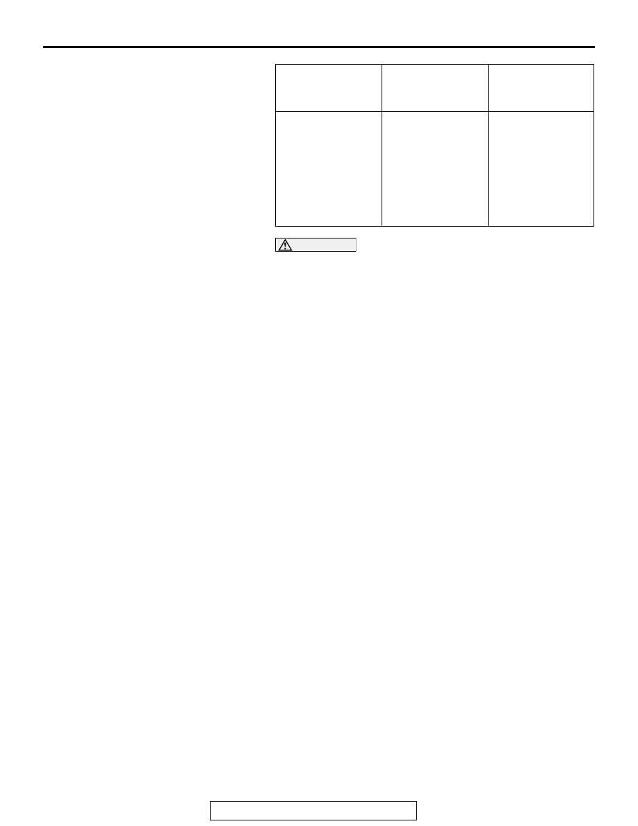
ENGINE

HEATED OXYGEN 
SENSOR OUTPUT 
VOLTAGE

REMARKS

When revving 
engine

0.6 

− 1.0 V

If you make the 
air/fuel ratio rich by 
revving the engine 
repeatedly, a 
normal heated 
oxygen sensor will 
output a voltage of 
0.6 

− 1.0 V.

ON-VEHICLE SERVICE

TSB Revision

MULTIPORT FUEL INJECTION (MFI)

13A-1004

<Right bank heated oxygen sensor (front)>
1. Using scan tool MB991958, observe HO

2

S reading. If 

values are unsatisfactory, or if a scan tool is not available, 
use the following procedure:

(1) Disconnect the heated oxygen sensor connector and 

connect special tool MD998464 to the connector on the 
heated oxygen sensor side.

(2) Make sure that there is continuity [4.5 

− 8.0 ohms at 20°C 

(68

°F)] between terminal No. 1 (red clip of special tool) 

and terminal No. 3 (blue clip of special tool) on the heated 
oxygen sensor connector

(3) If there is no continuity, replace the heated oxygen 

sensor.

(4) Warm up the engine until engine coolant is 80

°C (176°F) 

or higher.

(5) Perform a racing for 5 minutes or more with the engine 

speed of 4,500 r/min.

(6) Connect a digital voltage meter between terminal No. 2 

(black clip) and terminal No. 4 (white clip).

2. While repeatedly revving the engine, measure the heated 

oxygen sensor output voltage.

Standard value:

CAUTION

• Be very careful when connecting the jumper wire; 

incorrect connection can damage the heated oxygen 
sensor.

• Be careful the heater is broken when voltage of beyond 

8 volts is applied to the heated oxygen sensor heater.

NOTE: If the sufficiently high temperature [of approximate 
400

°

C (752

°

F) or more] is not reached although the heated 

oxygen sensor is normal, the output voltage would be possibly 
low although the rich air/fuel ratio. Therefore, if the output volt-
age is low, use a jumper wire to connect the terminal No. 1 (red 
clip of special tool) and the terminal No. 3 (blue clip of special 
tool) of the heated oxygen sensor with the positive terminal and 
the negative terminal of 8 volts power supply respectively, then 
check again.
3. If the sensor is defective, replace the heated oxygen sensor.

ENGINE

HEATED OXYGEN 
SENSOR OUTPUT 
VOLTAGE

REMARKS

When revving 
engine

0.6 

− 1.0 V

If you make the 
air/fuel ratio rich by 
revving the engine 
repeatedly, a 
normal heated 
oxygen sensor will 
output a voltage of 
0.6 

− 1.0 V.

AKX01624

HEATED
OXYGEN
SENSOR
EQUIPMENT
SIDE
CONNECTOR

MD998464

BLUE

RED

AC

AKX01624

HEATED
OXYGEN
SENSOR
COMPONENT
SIDE
CONNECTOR

MD998464

WHITE

BLACK

AL

ON-VEHICLE SERVICE

TSB Revision

MULTIPORT FUEL INJECTION (MFI)

13A-1005

NOTE: For removal and installation of the heated oxygen sen-
sor, refer to GROUP 15, Exhaust Pipe and Main Muffler 

P.15-13

.

.

<Left bank heated oxygen sensor (rear)>
1. Using scan tool MB991958, observe HO

2

S reading. If 

values are unsatisfactory, or if a scan tool is not available, 
use the following procedure:

(1) Disconnect the heated oxygen sensor connector and 

connect special tool MD998464 to the connector on the 
heated oxygen sensor side.

(2) Make sure that there is continuity [11 

− 18 ohms at 20°C 

(68

°F)] between terminal No. 1 (red clip of special tool) 

and terminal No. 3 (blue clip of special tool) on the heated 
oxygen sensor connector

(3) If there is no continuity, replace the heated oxygen 

sensor.

(4) Warm up the engine until engine coolant is 80

°C (176°F) 

or higher.

(5) Perform a racing for 5 minutes or more with the engine 

speed of 4,500 r/min.

(6) Connect a digital voltage meter between terminal 2 (black 

clip) and terminal No. 4 (white clip).

2. While repeatedly revving the engine, measure the heated 

oxygen sensor output voltage.

Standard value:

ENGINE

HEATED OXYGEN 
SENSOR OUTPUT 
VOLTAGE

REMARKS

When revving 
engine

0.6 

− 1.0 V

If you make the 
air/fuel ratio rich by 
revving the engine 
repeatedly, a 
normal heated 
oxygen sensor will 
output a voltage of 
0.6 

− 1.0 V.

AKX01624

HEATED
OXYGEN
SENSOR
EQUIPMENT
SIDE
CONNECTOR

MD998464

BLUE

RED

AC

AKX01624

HEATED
OXYGEN
SENSOR
COMPONENT
SIDE
CONNECTOR

MD998464

WHITE

BLACK

AL

ON-VEHICLE SERVICE

TSB Revision

MULTIPORT FUEL INJECTION (MFI)

13A-1006

CAUTION

• Be very careful when connecting the jumper wire; 

incorrect connection can damage the heated oxygen 
sensor.

• Be careful the heater is broken when voltage of beyond 

8 volts is applied to the heated oxygen sensor heater.

NOTE: If the sufficiently high temperature [of approximate 
400

°

C (752

°

F) or more] is not reached although the heated 

oxygen sensor is normal, the output voltage would be possibly 
low although the rich air/fuel ratio. Therefore, if the output volt-
age is low, use a jumper wire to connect the terminal No. 1 (red 
clip of special tool) and the terminal No. 3 (blue clip of special 
tool) of the heated oxygen sensor with the positive terminal and 
the negative terminal of 8 volts power supply respectively, then 
check again.
3. If the sensor is defective, replace the heated oxygen sensor.
NOTE: For removal and installation of the heated oxygen sen-
sor, refer to GROUP 15, Exhaust Pipe and Main Muffler 

P.15-13

.

.

<Right bank heated oxygen sensor (rear)>
1. Using scan tool MB991958, observe HO

2

S reading. If 

values are unsatisfactory, or if Scan tool is not available, use 
the following procedure:

(1) Disconnect the heated oxygen sensor connector and 

connect special tool MB991316 to the connector on the 
heated oxygen sensor side.

(2) Make sure that there is continuity [11 

− 18 ohms at 20°C 

(68

°F)] between terminal No. 1 (red clip of special tool) 

and terminal No. 3 (blue clip of special tool) on the heated 
oxygen sensor connector

(3) If there is no continuity, replace the heated oxygen 

sensor.

(4) Warm up the engine until engine coolant is 80

°C (176°F) 

or higher.

(5) Perform a racing for 5 minutes or more with the engine 

speed of 4,500 r/min.

(6) Connect a digital voltage meter between terminal No. 2 

(black clip) and terminal No. 4 (white clip).

2. While repeatedly revving the engine, measure the heated 

oxygen sensor output voltage.

AKX01624 AB

MB991316

HEATED
OXYGEN
SENSOR
EQUIPMENT
SIDE
CONNECTOR

BLUE

RED

AKX01624

HEATED
OXYGEN
SENSOR
COMPONENT
SIDE
CONNECTOR

MB991316

WHITE

BLACK

AN


Content   ..  377  378  379  380   ..