Mitsubishi Montero (2004+). Manual - part 344
 

  Index      Mitsubishi     Mitsubishi Montero - service repair manual 2004 year


Search            


Content   ..  342  343  344  345   ..


Mitsubishi Montero (2004+). Manual - part 344


MULTIPORT FUEL INJECTION (MFI) DIAGNOSIS

TSB Revision

MULTIPORT FUEL INJECTION (MFI)

13A-863

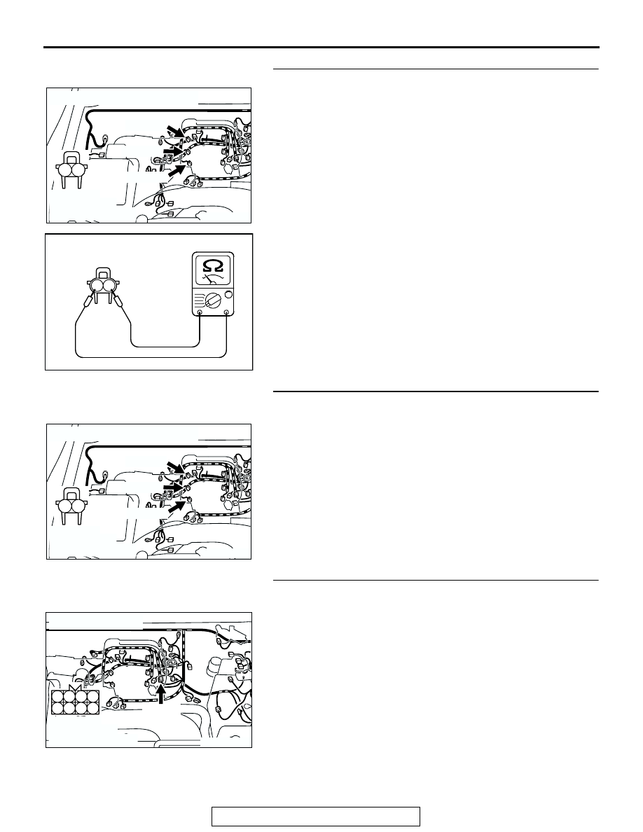
STEP 9. Check the right bank injector.
(1) Remove the intake manifold.
(2) Disconnect the right bank injector connector, which 

deviates from the standard value at Step 7.

(3) Measure the resistance between injector side connector 

terminal No. 1 and No. 2.

Standard value: 13 

 16 ohms [at 20°C (68°F)]

Q: Is the resistance between 13 and 16 ohms [at 20

°

(68

°F)]?

YES : Go to Step 10.
NO :  Replace the injector. Then confirm that the 

malfunction symptom is eliminated.

STEP 10. Check harness connector B-01 or B-02 or B-03 at 
right bank injector for damage.
(1) Check the injector connector, which deviated from the 

standard value listed in Step 7.

Q: Is the harness connector in good condition?

YES : Repair harness wire between injector intermediate 

connector and right bank injector connector because 
of harness damage. Then confirm that the 
malfunction symptom is eliminated.

NO :  Repair or replace it. Refer to GROUP 00E, Harness 

Connector Inspection 

P.00E-2

. Then confirm that the 

malfunction symptom is eliminated.

STEP 11. Check harness connector B-44 at the injector 
intermediate connector for damage.
Q: Is the harness connector in good condition?

YES : Go to Step 12.
NO :  Repair or replace it. Refer to GROUP 00E, Harness 

Connector Inspection 

P.00E-2

. Then confirm that the 

malfunction symptom is eliminated.

AK200950

1

2

B-03(GR)

B-02(GR)

B-01(GR)

CONNECTORS: B-01, B-02, B-03

AB

HARNESS 
CONNECTOR: 
COMPONENT SIDE

AKX01414AB

INJECTOR SIDE
CONNECTOR

1 2

AK200950

1

2

B-03(GR)

B-02(GR)

B-01(GR)

CONNECTORS: B-01, B-02, B-03

AB

HARNESS 
CONNECTOR: 
COMPONENT SIDE

AK200949

3

4

7

8

1

2

5

6

B-44(B)

CONNECTOR: B-44

AB

HARNESS 
CONNECTOR: 
COMPONENT SIDE

MULTIPORT FUEL INJECTION (MFI) DIAGNOSIS

TSB Revision

MULTIPORT FUEL INJECTION (MFI)

13A-864

STEP 12. Check harness connector B-11, B-33, B-35 at the 
left bank injector for damage.
Q: Is the harness connector in good condition?

YES : Go to Step 13.
NO :  Repair or replace it. Refer to GROUP 00E, Harness 

Connector Inspection 

P.00E-2

. Then confirm that the 

malfunction symptom is eliminated.

STEP 13. Check the harness connector D-132 at the PCM 
for damage.
Q: Is the harness connector in good condition?

YES : Go to Step 14.
NO :  Repair or replace it. Refer to GROUP 00E, Harness 

Connector Inspection 

P.00E-2

. Then confirm that the 

malfunction symptom is eliminated.

AK201292

1

2

B-11(GR)

B-35(GR)

B-33(GR)

CONNECTORS: B-11, B-33, B-35

AB

HARNESS 
CONNECTORS: 
COMPONENT SIDE

AK200938

2

3

4

5

6

7

8

9

1

10

14

15

16

17

18

19

20

21

22

23

24

25

26

27

11

12

13

AB

CONNECTOR: D-132

HARNESS CONNECTOR: 
COMPONENT SIDE

PCM

D-132(GR)

MULTIPORT FUEL INJECTION (MFI) DIAGNOSIS

TSB Revision

MULTIPORT FUEL INJECTION (MFI)

13A-865

STEP 14. Check for harness damage between injector 
connector and PCM connector.

a. Check the harness wire between injector connector 

B-01 (terminal No. 2) and PCM connector D-132 (termi-
nal No. 1) at No. 1 cylinder injector.

b. Check the harness wire between injector connector 

B-33 (terminal No. 2) and PCM connector D-132 (termi-
nal No. 5) at No. 2 cylinder injector.

c. Check the harness wire between injector connector 

B-02 (terminal No. 2) and PCM connector D-132 (termi-
nal No. 14) at No. 3 cylinder injector.

d. Check the harness wire between injector connector 

B-35 (terminal No. 2) and PCM connector D-132 (termi-
nal No. 21) at No. 4 cylinder injector.

e. Check the harness wire between injector connector 

B-03 (terminal No. 2) and PCM connector D-132 (termi-
nal No. 2) at No. 5 cylinder injector.

f. Check the harness wire between injector connector 

B-11 (terminal No. 2) and PCM connector D-132 (termi-
nal No. 6) at No. 6 cylinder injector.

Q: Is the harness wire in good condition?

YES : Check the following items, and repair or replace the 

defective items.
a.Check the ignition coil, spark plugs, spark plug 

cables.

b.Check if the injectors are clogged.
c.Check the compression pressure.
d.Check if the foreign materials (water, kerosene, 

etc.) got into fuel.

e.Check the EGR valve.

Then confirm that the malfunction symptom is 

eliminated.

NO :  Repair it. Then confirm that the malfunction symptom 

is eliminated.

INSPECTION PROCEDURE 8: Unstable Idle (Rough Idle, Hunting).

.

COMMENT

• In cases such as the above, the cause is proba-

bly the air/fuel mixture or electronic control throt-
tle valve system. Other systems affecting idle 
quality include the ignition system and compres-
sion.

.

TROUBLESHOOTING HINTS (The most likely 
causes for this case: )

• Malfunction of the ignition system.

• Malfunction of air/fuel ratio control system.

• Malfunction of the electronic control throttle valve 

system.

• Malfunction of the evaporative emission purge 

solenoid system.

• Malfunction of the EGR valve.

• Poor compression pressure.

• Vacuum leak.

AK200960

1

2

B-03(GR)

B-11(GR)

B-35(GR)

B-33(GR)

B-02(GR)

B-01(GR)

CONNECTORS: B-01, B-02, B-03, B-11, 

B-33, B-35

AB

HARNESS CONNECTOR: 
COMPONENT SIDE

AK200938

2

3

4

5

6

7

8

9

1

10

14

15

16

17

18

19

20

21

22

23

24

25

26

27

11

12

13

AB

CONNECTOR: D-132

HARNESS CONNECTOR: 
COMPONENT SIDE

PCM

D-132(GR)

MULTIPORT FUEL INJECTION (MFI) DIAGNOSIS

TSB Revision

MULTIPORT FUEL INJECTION (MFI)

13A-866

DIAGNOSIS

Required Special Tools:

• MB991958: Scan Tool (MUT-III Sub Assembly)

• MB991824: V.C.I.

• MB991827: USB Cable

• MB991911: Main Harness B

STEP 1. Check if the battery terminal is disconnected
Q: Has the battery terminal been disconnected lately?

YES : Start the engine and let it run at idle for approximate 

10 minutes after engine warm up. Then, if a 
malfunction occurs, go to Step 2.

NO :  Go to Step 2.

STEP 2. Using scan tool MB991958, read the diagnostic 
trouble code (DTC).

CAUTION

To prevent damage to scan tool MB991958, always turn the 
ignition switch is to the "LOCK" (OFF) position before con-
necting or disconnecting scan tool MB991958.
(1) Connect scan tool MB991958 to the data link connector.
(2) Turn the ignition switch to the "ON" position.
(3) Read the DTC.
(4) Turn the ignition switch to the "LOCK" (OFF) position.
Q: Is the DTC set?

YES : Refer to Diagnostic Trouble Code Chart 

P.13A-4

.

NO :  Go to Step 3.

STEP 3. Check the engine idling state.
Q: Is it hunting remarkably?

YES : Go to Step 4.
NO :  Go to Step 5.

STEP 4. Check the following items.
(1) Carry out the following cleaning.

a. Refer to On-vehicle Service 

− Clean the throttle valve 

area 

P.13A-993

.

(2) After cleaning, confirm that the malfunction symptom is 

eliminated.

Q: Is the malfunction symptom resolved?

YES : The check is completed.

AK302970

AB

MB991911

MB991824

MB991827


Content   ..  342  343  344  345   ..