Mitsubishi Montero (2004+). Manual - part 171
 

  Index      Mitsubishi     Mitsubishi Montero - service repair manual 2004 year


Search            


Content   ..  169  170  171  172   ..


Mitsubishi Montero (2004+). Manual - part 171


MULTIPORT FUEL INJECTION (MFI) DIAGNOSIS

TSB Revision

MULTIPORT FUEL INJECTION (MFI)

13A-171

Judgment Criteria

• Input voltage supplied to the PCM interface circuit 

is higher than 4.5 volts when 5 volts is applied to 
the right bank heated oxygen sensor (front) out-
put line via a resistor.

.

OBD-II DRIVE CYCLE PATTERN
 Refer to Diagnostic Function 

− OBD-II Drive Cycle − 

Procedure 6 

− Other Monitor 

P.13A-4

.

.

TROUBLESHOOTING HINTS (The most likely 
causes for this code to be set are: )

• Right bank heated oxygen sensor (front) deterio-

rated.

• Short circuit in right bank heated oxygen sensor 

(front) output line or harness damage.

• Open circuit in right bank heated oxygen sensor 

(front) ground line or harness damage.

• Connector damage.

• PCM failed.

DIAGNOSIS

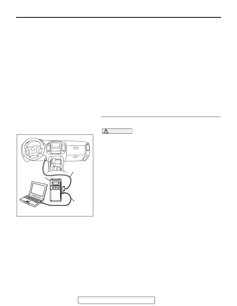
Required Special Tools:

• MB991958: Scan tool (MUT-III Sub Assembly)

• MB991824: V.C.I.

• MB991827: USB Cable

• MB991911: Main Harness B

• MD998464: Test Harness

STEP 1. Using scan tool MB991958, check data list item 39: 
Heated Oxygen Sensor Bank 1, Sensor 1 (right front).

CAUTION

To prevent damage to scan tool MB991958, always turn the 
ignition switch to the "LOCK" (OFF) position before con-
necting or disconnecting scan tool MB991958.
(1) Connect scan tool MB991958 to the data link connector.
(2) Start the engine and run at idle.
(3) Set scan tool MB991958 to the data reading mode for item 

39, Heated Oxygen Sensor Bank 1, Sensor 1 (right front).

• Warming up the engine. When the engine is revved, the 

output voltage should be 0.6 to 1.0 volt.

• Warming up the engine. When the engine is idling, the 

output voltage should repeat 0.4 volt and 0.6 to 1.0 volt 
alternately.

(4) Turn the ignition switch to the "LOCK" (OFF) position.
Q: Is the sensor operating properly?

YES : It can be assumed that this malfunction is intermittent. 

Refer to GROUP 00, How to Use 
Troubleshooting/Inspection Service Points 

P.00-6

NO :  Go to Step 2.

AK302970

AB

MB991911

MB991824

MB991827

MULTIPORT FUEL INJECTION (MFI) DIAGNOSIS

TSB Revision

MULTIPORT FUEL INJECTION (MFI)

13A-172

STEP 2. Measure the sensor output voltage at right bank 
heated oxygen sensor (front) connector B-07 by 
backprobing
(1) Do not disconnect the connector B-07.
(2) Start the engine and run at idle.

(3) Measure the voltage between terminal No. 4 and ground by 

backprobing.

• Warming up the engine. When the engine is 2,500 r/min, 

the output voltage should repeat 0 to 0.8 volt alternately.

(4) Turn the ignition switch to the "LOCK" (OFF) position.
Q: Is the voltage normal?

YES : Go to Step 3.
NO :  Go to Step 7.

AK201274

1

2

3

4

CONNECTOR: B-07

B-07(B)

AB

HARNESS 
CONNECTOR: 
COMPONENT SIDE

RIGHT BANK
HEATED OXYGEN
SENSOR (FRONT)

AKX01532AC

3

1 2

4

B-07 HARNESS 
CONNECTOR: 
HARNESS SIDE

MULTIPORT FUEL INJECTION (MFI) DIAGNOSIS

TSB Revision

MULTIPORT FUEL INJECTION (MFI)

13A-173

STEP 3. Measure the sensor output voltage at PCM 
connector D-135 by backprobing
(1) Do not disconnect the connector D-135.
(2) Start the engine and run at idle.

(3) Measure the voltage between terminal No. 109 and ground 

by backprobing.

• Warming up the engine. When the engine is 2,500 r/min, 

the output voltage should repeat 0 to 0.8 volt alternately.

(4) Turn the ignition switch to the "LOCK" (OFF) position.
Q: Is the voltage normal?

YES : Go to Step 4.
NO :  Go to Step 6.               

AK200947

91

92

93

94

95

96

97

98

99

100

101

102

103

104

105

106

107

108

109

110

111

112

113

114

115

116

117

118

119

120

CONNECTOR: D-135

HARNESS CONNECTOR: 
COMPONENT SIDE

AB

PCM

D-135(GR)

AK201396

9192

939495

96979899

100 101102103

104

105106

107108109

110111112

113114

115116117

118119120

AB

D-135 HARNESS 
CONNECTOR:
HARNESS SIDE

MULTIPORT FUEL INJECTION (MFI) DIAGNOSIS

TSB Revision

MULTIPORT FUEL INJECTION (MFI)

13A-174

STEP 4. Check harness connector B-07 at right bank 
heated oxygen sensor (front) and harness connector 
D-135 at PCM for damage.
Q: Is the harness connector in good condition?

YES : Go to Step 5.
NO :  Repair or replace it. Refer to GROUP 00E, Harness 

Connector Inspection 

P.00E-2

. Then go to Step 15. 

AK201274

1

2

3

4

CONNECTOR: B-07

B-07(B)

AB

HARNESS 
CONNECTOR: 
COMPONENT SIDE

RIGHT BANK
HEATED OXYGEN
SENSOR (FRONT)

AK200947

91

92

93

94

95

96

97

98

99

100

101

102

103

104

105

106

107

108

109

110

111

112

113

114

115

116

117

118

119

120

CONNECTOR: D-135

HARNESS CONNECTOR: 
COMPONENT SIDE

AB

PCM

D-135(GR)


Content   ..  169  170  171  172   ..