Mitsubishi Montero (2004+). Manual - part 1223


  Index      Mitsubishi     Mitsubishi Montero - service repair manual 2004 year


Search            


Content   ..  1221  1222  1223  1224   ..


Mitsubishi Montero (2004+). Manual - part 1223


SIDE IMPACT SENSOR

TSB Revision

SUPPLEMENTAL RESTRAINT SYSTEM (SRS)

52B-227

SIDE IMPACT SENSOR

REMOVAL AND INSTALLATION

M1524004600340

A side impact sensor is installed behind the center pillar trim on both driver and passenger sides of the vehi-
cle.

WARNING

Never attempt to disassemble or repair the side impact sensor. If faulty, replace it. 

Do not drop or subject the side impact sensor to impact or vibration. Replace the side 
impact sensor, if dents, cracking, deformation, or rust are present. 

Replace the side impact sensor after the air bag has deployed. 

NOTE: The illustration above shows the side impact sensor (RH). The position of the side impact sensor (LH) 
is symmetrical to this.

Pre-removal Operation
• Turn the ignition key to "LOCK" (OFF) position.

• Front Seat Belt Removal (Refer to GROUP 52A, Front 

Seat Belt 

P.52A-29

).

• Center Pillar Trim, Lower Removal (Refer to GROUP 52A, 

Trims 

P.52A-8

).

Post-installation Operation
• Center Pillar Trim, Lower Installation (Refer to GROUP 

52A, Trims 

P.52A-8

).

• Front Seat Belt Installation (Refer to GROUP 52A, Front 

Seat Belt 

P.52A-29

).

ACX01489AB

1

3

CENTER PILLAR

4.9 ± 1.0 N·m
43 ± 8 in-lb

2

FORWARD

REMOVAL STEPS

<<A>>

1.

NEGATIVE (-) BATTERY CABLE 
CONNECTION

2.

FRONT NOISE PROTECTOR

3.

SIDE IMPACT SENSOR

INSTALLATION STEPS

>>A<<

PRE-INSTALLATION INSPECTION

>>B<<

3.

SIDE IMPACT SENSOR

2.

FRONT NOISE PROTECTOR

1.

NEGATIVE (-) BATTERY CABLE 
CONNECTOR

>>C<<

POST-INSTALLATION 
INSPECTION

SIDE IMPACT SENSOR

TSB Revision

SUPPLEMENTAL RESTRAINT SYSTEM (SRS)

52B-228

REMOVAL SERVICE POINT

.

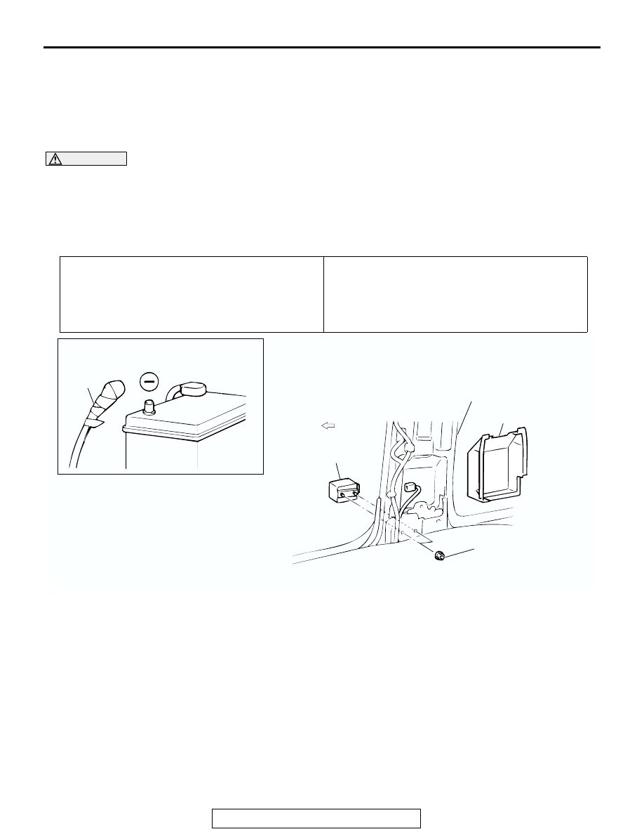
<<A>> NEGATIVE (

) BATTERY CABLE DISCONNECTION

DANGER

Wait at least 60 seconds after disconnecting the bat-
tery cable before doing any further work (Refer to 

P.52B-18

).

WARNING

Battery posts, terminals and related accessories con-
tain lead and lead compounds. WASH HANDS AFTER 
HANDLING.

Disconnect the negative (

−) battery cable from the battery and 

tape the terminal to prevent accidental connection and air 
bag(s) deployment.

INSTALLATION SERVICE POINTS

.

>>A<< PRE-INSTALLATION INSPECTION
Check the side impact sensor for dents, breakage and bending 
and measure the resistance between the terminals, even when 
installing a new side impact sensor.

.

>>B<< SIDE IMPACT SENSOR INSTALLATION

WARNING

If the side impact sensor is not installed securely and 
correctly, the side air bag may not operate normally.

Securely connect the connector.

.

ACX00583

INSULATING TAPE

BATTERY

BATTERY CABLE (–)

AC

ACX00591

CENTER 
PILLAR

FORWARD

AB

SIDE IMPACT
SENSOR

SEAT BELTS WITH PRE-TENSIONER

TSB Revision

SUPPLEMENTAL RESTRAINT SYSTEM (SRS)

52B-229

>>C<< POST-INSTALLATION INSPECTION

1. Reconnect the negative (

−) battery cable.

2. Turn the ignition switch to "ON" position.
3. Does the "SRS" warning light illuminate for approximately 

seven seconds, and then remain off for at least five sec-
onds after turning "OFF"?

4. If yes, the SRS system is functioning properly. If no, refer to 

P.52B-22

.

INSPECTION

M1524004700295

WARNING

If a dent, crack, deformation or rust is detected, 
replace with a new sensor.

NOTE: For checking of the side impact sensor other than 
described above, refer to the section concerning SRS diagno-
sis (Refer to 

P.52B-21

).

• Check the side impact sensor and bracket for dents, cracks 

or deformation.

• Check the connector for damage, and terminal for deforma-

tion.

• Check that there is no bending or corrosion in the center pil-

lar.

SEAT BELTS WITH PRE-TENSIONER

REMOVAL AND INSTALLATION

M1524004100345

WARNING

Never attempt to disassemble or repair the seat belt pre-tensioner. If faulty, replace it.

Be extremely careful when handling the seat with pre-tensioner. Do not subject it to 
shocks, drop it, bring it close to strong magnets or allow contact with water, grease or oil. 
Always replace it with a new part if any dents, cracks or deformation is found.

Do not place anything on top of the seat belt pre-tensioner.

Do not expose the seat belt pre-tensioner to temperatures over 90

°

C (194

°

F).

After operating the seat belt pre-tensioner, replace the seat belt pre-tensioner with a new 
part.

Gloves and protective goggles should be worn when handling a seat belt pre-tensioner 
once it has been used.

If disposing of a seat belt with pre-tensioner which has not yet been operated, its seat belt 
pre-tensioner should be operated first before disposal (Refer to 

P.52B-234

).

ACX01667

AT

TEMP

SRS

P
R
N
D

5
4
3
2
1

x1000r/min

2

3

4

5

6

7

8

1

AB

SRS WARNING LIGHT

SEAT BELTS WITH PRE-TENSIONER

TSB Revision

SUPPLEMENTAL RESTRAINT SYSTEM (SRS)

52B-230

Required Special Tool: 

• MB991958: Scan Tool (MUT-III Sub Assembly)

• MB991824: Vehicle Communication Interface 

(V.C.I.)

• MB9991827: MUT-III USB Cable

• MB991911: MUT-III Main Harness B (Vehicles 

without CAN communication system)

AC204135

2

3

44 ± 10 N·m
33 ± 7 ft-ib

3

44 ± 10 N·m
33 ± 7 ft-ib

1

4

AB

44 ± 10 N·m
33 ± 7 ft-ib

REMOVAL STEPS

<<A>>

1. NEGATIVE (

−) BATTERY CABLE 

CONNECTION

2. SASH GUIDE COVER
• CENTER PILLAR TRIM, LOWER 

(REFER TO GROUP 52A, TRIMS 

P.52A-3

).

3. OUTER SEAT BELT CONNECTION
4. SEAT BELT WITH PRE-TENSIONER

INSTALLATION STEPS

>>A<<

• PRE-INSTALLATION INSPECTION

4. SEAT BELT WITH PRE-TENSIONER
3. OUTER SEAT BELT CONNECTION
• CENTER PILLAR TRIM, LOWER 

(REFER TO GROUP 52A, TRIMS 

P.52A-3

).

2. SASH GUIDE COVER

1. NEGATIVE (

−) BATTERY CABLE 

CONNECTION

>>B<<

• POST-INSTALLATION INSPECTION

INSTALLATION STEPS (Continued)


Content   ..  1221  1222  1223  1224   ..