Content .. 1108 1109 1110 1111 ..
Mitsubishi Montero (2004+). Manual - part 1110
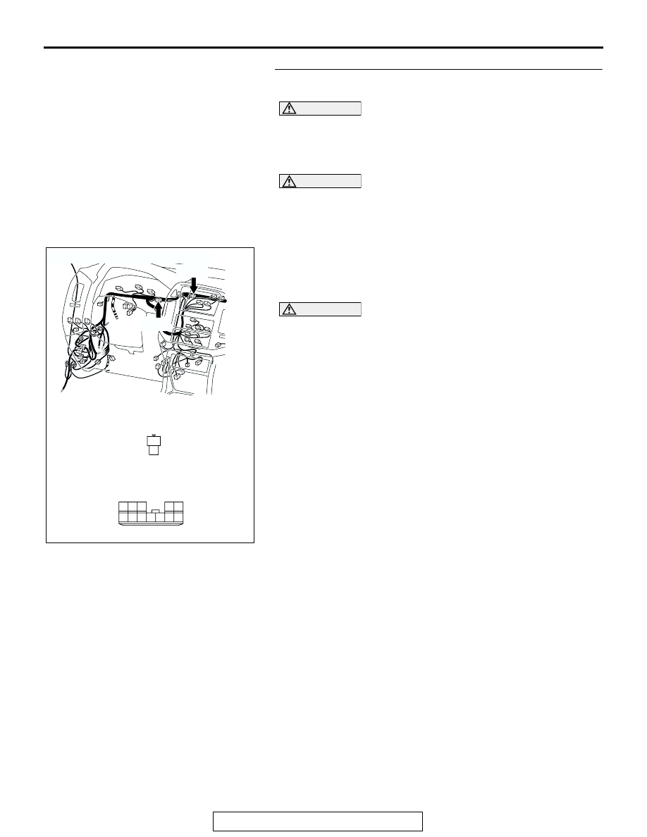
M-ASTC DIAGNOSIS
TSB Revision
MITSUBISHI ACTIVE SKID AND TRACTION CONTROL SYSTEM
35C-151
STEP 22. Check the CAN bus line for open circuit. Measure
at joint connector (9) D-131 and resistor connector D-130.
CAUTION
Before checking CAN bus lines and their interconnected
components, "ground" yourself, by touching a metal
object such as an unpainted pipe, this will discharge any
potentially damaging static that may have built up.
CAUTION
When measuring resistance value or voltage in CAN bus
lines, use a digital multimeter. If not using a digital multim-
eter, the equipments, which are connected through the
CAN communication lines, may be damaged.
(1) Disconnect joint connector (9) D-131 and resistor connector
D-130, and measure the resistance between joint connector
(9) and the resistor connector.
(2) Turn the ignition switch to the LOCK (OFF) position.
CAUTION
Disconnect the negative battery terminal when measuring
the resistance value in the CAN bus line. If you fail to do
so, the equipments, which are connected through the CAN
communication lines, may be damaged.
(3) Disconnect the negative battery terminal.
AC204188
CONNECTORS: D-130, D-131
D-131
AQ
HARNESS SIDE
HARNESS SIDE
D-131
D-130
D-130
6
1
9 8
2
7
10
12 11
4
5
3
1
2