Mitsubishi Montero (2004+). Manual - part 1063


  Index      Mitsubishi     Mitsubishi Montero - service repair manual 2004 year


Search            


Content   ..  1061  1062  1063  1064   ..


Mitsubishi Montero (2004+). Manual - part 1063


ANTI-LOCK BRAKING SYSTEM (ABS) DIAGNOSIS

TSB Revision

ANTI-LOCK BRAKING SYSTEM (ABS)

35B-95

STEP 2 Check the ABS warning light bulb.
(1) Remove the combination meter (Refer to GROUP 54A, 

Combination Mete

P.54A-76

).

(2) Check the ABS warning light bulb.
Q: Is the bulb burned out?

YES : Replace the bulb and then go to Step 10.
NO :  Go to Step 3.

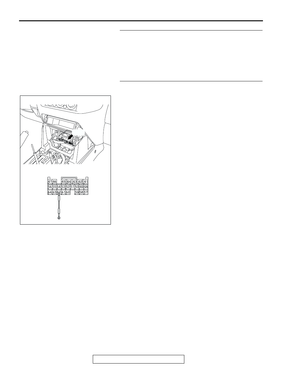
STEP 3. Check the ABS warning light circuit at 
M-ASTC-ECU connector E-120.
(1) Disconnect M-ASTC-ECU connector E-120 and measure at 

the harness side.

(2) Ground the terminal 62.
(3) Turn the ignition switch to the "ON" position. The ABS 

warning light should turn on.

Q: Is the ABS warning light turn on?

YES : Replace the M-ASTC-ECU and then go to Step 5.
NO :  Go to Step 4.

AC203901

AC204627

CONNECTOR: E-120

AS

E-120

HARNESS CONNECTOR:
COMPONENT SIDE

ANTI-LOCK BRAKING SYSTEM (ABS) DIAGNOSIS

TSB Revision

ANTI-LOCK BRAKING SYSTEM (ABS)

35B-96

STEP 4. Check the harness wires between combination 
meter connector D-03 terminal 56 and M-ASTC-ECU 
connector E-120 terminal 62.
NOTE: After inspecting combination meter connector D-03, 
intermediate connector E-110 and M-ASTC-ECU connector 
E-120, inspect the wire. If combination meter connector D-03, 
intermediate connector E-110 and M-ASTC-ECU connector 
E-120 are damaged, repair or replace them. Refer to GROUP 
00E, Harness Connector Inspection 

P.00E-2

.Then go to Step 

10.

AC204690 AC

CONNECTOR: D-03

D-03 (GR)

HARNESS CONNECTOR: 
COMPONENT SIDE

D-03

AC203901

AC204627AG

CONNECTOR: E-120

E-120

HARNESS CONNECTOR: 
COMPONENT SIDE

E-120

ANTI-LOCK BRAKING SYSTEM (ABS) DIAGNOSIS

TSB Revision

ANTI-LOCK BRAKING SYSTEM (ABS)

35B-97

Q: Is the harness wire between combination meter 

connector D-03 terminal 56 and M-ASTC-ECU connector 
E-120 terminal 62 damaged?
YES : 
Repair it and then go to Step 10.
NO :  Replace the combination meter (printed circuit board) 

and go to Step 10.

AC204385

CONNECTOR: E-110

AD

E-110

6

1

7

2

9

8

10

3

5

12

11

4

1314

ANTI-LOCK BRAKING SYSTEM (ABS) DIAGNOSIS

TSB Revision

ANTI-LOCK BRAKING SYSTEM (ABS)

35B-98

STEP 5. Check the harness wire between combination 
meter connector D-03 terminal 56 and valve relay 
connector B-21X terminal 2.
NOTE: After inspecting valve relay connector B-21X and inter-
mediate connector E-110, inspect the wire. If valve relay con-
nector B-21X and intermediate connector E-110 are damaged, 
repair or replace them. Refer to GROUP 00E, Harness Con-
nector Inspection 

P.00E-2

.Then go to Step 10.

Q: Is the harness wire between combination meter 

connector D-03 terminal 56 and valve relay connector 
B-21X terminal 2 damaged?
YES : 
Repair them and then go to Step 10.
NO :  Go to Step 6.

AC204690 AC

CONNECTOR: D-03

D-03 (GR)

HARNESS CONNECTOR: 
COMPONENT SIDE

D-03

AC204706

1

2

3

4

1

2

3

4

1

2

3

4

1

2

3

4

1

2

3

4

1

2

3

4

1

2

3

5

B-21X

CONNECTOR: B-21X

AB

RELAY BOX CONNECTOR

AC204385

CONNECTOR: E-110

AD

E-110

6

1

7

2

9

8

10

3

5

12

11

4

1314


Content   ..  1061  1062  1063  1064   ..