Mitsubishi Montero (2004+). Manual - part 1033


  Index      Mitsubishi     Mitsubishi Montero - service repair manual 2004 year


Search            


Content   ..  1031  1032  1033  1034   ..


Mitsubishi Montero (2004+). Manual - part 1033


ON-VEHICLE SERVICE

TSB Revision

BASIC BRAKE SYSTEM

35A-131

DISC BRAKE PAD CHECK AND REPLACEMENT

M1351002300246

NOTE: The brake pads have indicators that contact the brake 
disc when the brake pad thickness becomes 2 mm (0.08 inch), 
and emit a squealing sound to warn the driver.

CAUTION

• Whenever a pad must be replaced, replace both LH and 

RH wheel pads as a set to prevent the vehicle from pull-
ing to one side when braking.

CAUTION

If there is a significant difference in the thicknesses of the 
pads on the left and right sides, check the sliding condi-
tion of the piston, lock pin and guide pin.
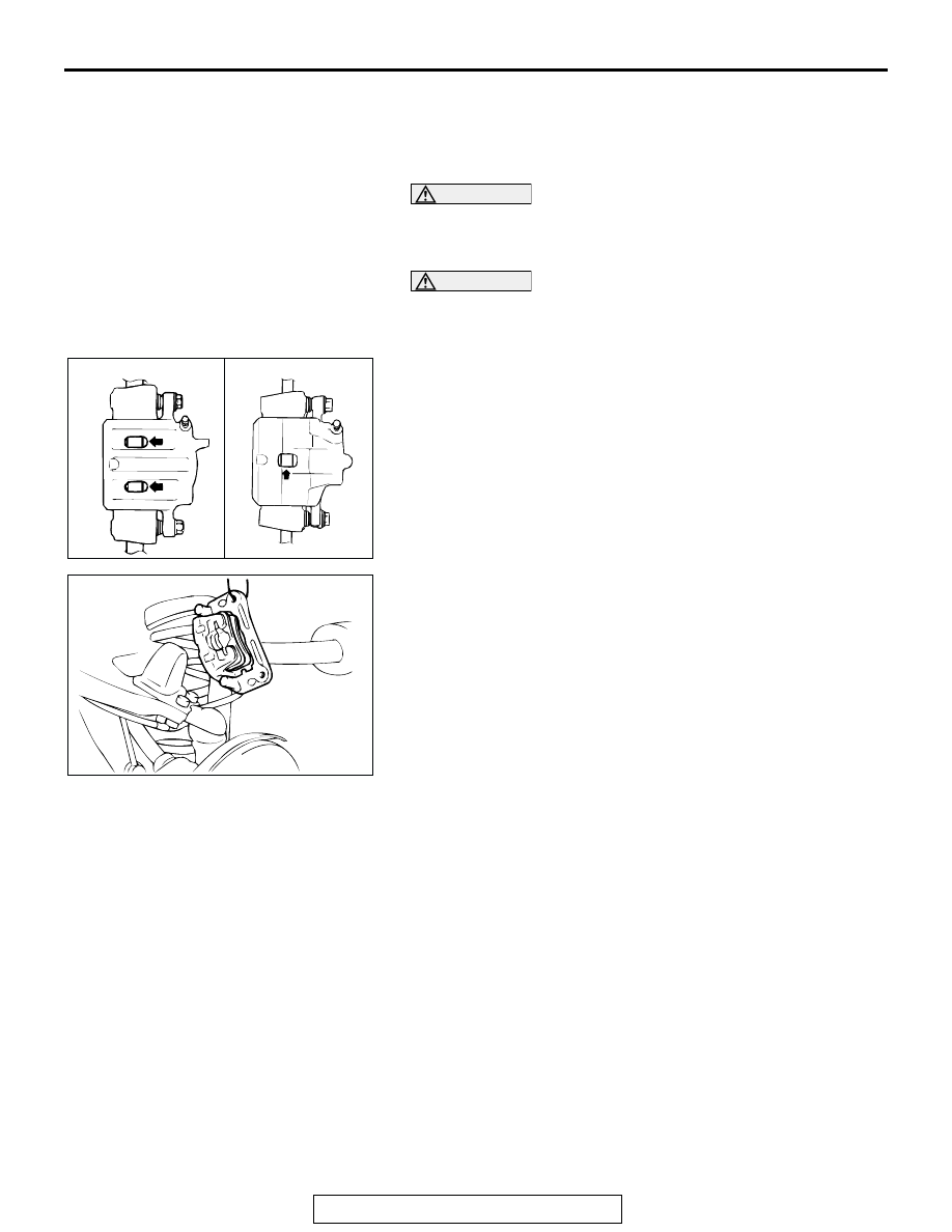
1. Check the brake pad thickness through the caliper body 

check port.

Standard value: 10.0 mm (0.39 inch)
Minimum limit: 2.0 mm (0.08 inch)

2. Remove the guide pin lock bolt. Lift the caliper assembly 

and secure it with a wire.

ACX00665

AB

FRONT

REAR

ACX00705

ON-VEHICLE SERVICE

TSB Revision

BASIC BRAKE SYSTEM

35A-132

3. Remove the following parts from caliper support.

(1) Pad and wear indicator assembly <FRONT>

Pad and clip assembly <REAR>

(2) Pad assembly
(3) Clip
(4) Shim
(5) Shim B <REAR>
(6) Shim A <REAR>

4. Measure the hub torque before and after pad installation. 

Follow the procedure: 

• FRONT: Refer to 

P.35A-143

.

• REAR: Refer to 

P.35A-149

.

CAUTION

Do not apply excessive grease. Excessive grease may 
cause brake performance to become poor.
5. For rear disc bake, apply brake grease SAE J310, NLGI 

number 1 to the following positions before installing the pad.

• Pad assembly and shim A contact surface

• Inner shim A and shim B contact surface

6. Install the pad and caliper assembly, and check the brake 

drag force.

• FRONT: Refer to 

P.35A-143

.

• REAR: Refer to 

P.35A-149

.

AC204544AB

FRONT

REAR

3

3

3

3

1

1

2

2

4

4

6

5

AC000886

SHIM A

SHIM B

PAD ASSEMBLY

<REAR>

AD

ON-VEHICLE SERVICE

TSB Revision

BASIC BRAKE SYSTEM

35A-133

DISC BRAKE ROTOR CHECK

M1351002900215

CAUTION

Disc brakes must be kept within the allowable 
service values in order to maintain normal brake 
operation.
Before turning the brake disc, the following condi-
tions should be checked:

BRAKE DISC THICKNESS CHECK

M1351002400254

1. Remove dirt and rust from the brake disc surface.
2. Using a micrometer, measure disc thickness at eight 

positions, approximately 45 degrees apart and 10 mm (0.4 
inch) in from the outer edge of the disc.

FRONT BRAKE DISC
Standard value: 26.0 mm (1.02 inch)
Minimum limit: 24.4 mm (0.96 inch)
REAR BRAKE DISC
Standard value: 22.0 mm (0.87 inch)
Minimum limit: 20.4 mm (0.80 inch)

NOTE: Thickness variation (at least 8 positions) should not 
be more than 0.015 mm (0.0006 inch).

INSPECTION ITEM

REMARK

Scratches, rust, saturated lining 
materials and wear

• If the vehicle is not driven for a long period of time, sections of the 

discs that are not in contact with the pads will become rusty, causing 
noise and shuddering.

• If grooves and scratches resulting from excessive disc wear are not 

removed prior to installing a new pad assembly, there will be 
inadequate contact between the disc and the lining (pad) until the 
pads conform to the disc.

Run-out

Excessive run-out of the discs will increase the pedal depression 
resistance due to piston kickback.

Change in thickness (parallelism) If the thickness of the disc changes, this will cause pedal pulsation, 

shuddering and surging.

Warping (flatness) or distortion

Overheating and improper handling while servicing will cause warping 
or distortion.

ACX00668

ON-VEHICLE SERVICE

TSB Revision

BASIC BRAKE SYSTEM

35A-134

CAUTION

• After a new brake disc is installed, always grind the 

brake disc with a on-car type brake lathe. If this step is 
not carried out, the brake disc run-out will exceed the 
specified value, resulting in judder.

• When the on-car type lathe is used, first install a M12 

flat washer on the stud bolt in the brake disc side 
according to the figure, and then install the adapter. If 
the adapter is installed without a M12 flat washer, the 
brake disc rotor may be deformed, resulting in inaccu-
rate grinding.

• Grind the brake disc with all wheel nuts diagonally and 

equally tightened to the specified torque 100 N

m (74 

ft-lb). When all numbers of wheel nuts are not used, or 
the tightening torque is excessive or not equal, the 
brake disc rotor or drum may be deformed, resulting in 
judder.

3. If the disc thickness is less than the limits, replace it with a 

new one. If thickness variation exceeds the specification, 
turn rotor with an on-car type brake lathe ("Accuturn-8750" 
or equivalent).
If the calculated final thickness after turning the rotor is less 
than the standard value, replace the disc.

BRAKE DISC RUN-OUT CHECK AND 
CORRECTION

M1351009400404

1. Remove the caliper support; then raise the caliper assembly 

upward and secure it with a wire.

2. Inspect the disc surface for grooves, cracks and rust. Clean 

the disc thoroughly and remove all rust.

3. Fix the disc with a hub nut temporarily.
4. Place a dial gauge approximately 5 mm (0.2 inch) from the 

outer circumference of the brake disc, and measure the 
run-out of the disc.

Limit: 0.06 mm (0.002 inch)

5. If the run-out of the brake disc is limit value or more, correct 

it as follows:

(1) Place a mating mark on both the wheel stud and disc with 

chalk where the run-out is greatest.

AC005154 AB

M12 PLANE 
WASHER

M12 PLANE 
WASHER

ACX00669


Content   ..  1031  1032  1033  1034   ..