Mitsubishi Montero (2004+). Manual - part 1025


  Index      Mitsubishi     Mitsubishi Montero - service repair manual 2004 year


Search            


Content   ..  1023  1024  1025  1026   ..


Mitsubishi Montero (2004+). Manual - part 1025


HYDRAULIC BRAKE BOOSTER (HBB) DIAGNOSIS

TSB Revision

BASIC BRAKE SYSTEM

35A-99

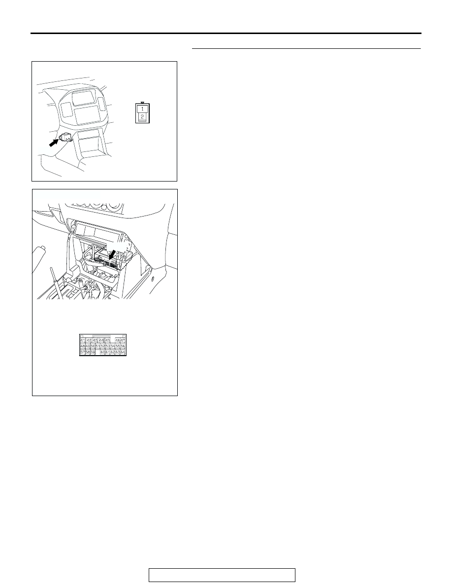
STEP 1. Check the following connectors.

• Buzzer connector E-107

• M-ASTC-ECU connector E-120

Check connectors for loose, corroded or damaged terminals, or 
terminals pushed back in the connector.
Q: Are the connectors and terminals in good condition?

YES : Go to Step 2.
NO :  Repair the faulty connector or terminal and then go to 

Step 7.

AC204692 AB

CONNECTOR: E-107

E-107

BUZZER 
CONNECTOR

E-107

AC203901

AC204627AE

CONNECTOR: E-120

M-ASTC-ECU CONNECTOR

E-120

E-120

HYDRAULIC BRAKE BOOSTER (HBB) DIAGNOSIS

TSB Revision

BASIC BRAKE SYSTEM

35A-100

STEP 2. Check the buzzer circuit at M-ASTC-ECU harness 
connector E-120.

(1) Disconnect M-ASTC-ECU connector E-120 and check at 

the harness connector (component side).

(2) Turn the ignition switch to the "ON" position.

(3) Connect terminal 54 to body ground.
Q: Does the buzzer sound?

YES : Replace the M-ASTC-ECU (Refer to GROUP 35C, 

M-ASTC-ECU 

P.35C-213

). Then go to Step 7.

NO :  Go to Step 3.

STEP 3. Check the buzzer.

(1) Remove the buzzer (Refer to 

P.35A-142

).

(2) Connect the battery to the buzzer as shown on the 

illustration.

Q: Does the buzzer sound?

YES : Go to Step 4.
NO :  Replace the buzzer (Refer to 

P.35A-142

). Then go to 

Step 7.

AC203901

AC204627AE

CONNECTOR: E-120

M-ASTC-ECU CONNECTOR

E-120

E-120

AC204726 AB

E-120

HARNESS CONNECTOR: 
COMPONENT SIDE

ACX00680AB

HYDRAULIC BRAKE BOOSTER (HBB) DIAGNOSIS

TSB Revision

BASIC BRAKE SYSTEM

35A-101

STEP 4. Check the buzzer power supply circuit at buzzer 
harness connector E-107.

(1) Disconnect buzzer connector E-107, and measure at the 

harness connector (component side).

(2) Turn the ignition switch to the "ON" position.

(3) Measure the voltage between terminal 1 and ground. The 

voltage should measure approximately 12 volts (battery 
positive voltage).

Q: Is battery positive voltage (approximately 12 volts) 

present?
YES : 
Go to Step 5.
NO :  Go to Step 6.

AC204692 AB

CONNECTOR: E-107

E-107

BUZZER 
CONNECTOR

E-107

ACX01879

2

1

AC

HARNESS CONNECTOR: 
COMPONENT SIDE

E-107

HYDRAULIC BRAKE BOOSTER (HBB) DIAGNOSIS

TSB Revision

BASIC BRAKE SYSTEM

35A-102

STEP 5. Check the following harness wire.

• The wire between buzzer connector E-107 (terminal 2) and 

M-ASTC-ECU connector E-120 (terminal 54) 

Q: Is the harness wire damaged?

YES : Repair or replace it and then go to Step 7.
NO :  Go to Step 7.

AC204727AB

CONNECTOR: E-107

E-107

HARNESS 
CONNECTOR: 
COMPONENT 
SIDE

E-107

AC203901

AC204627AG

CONNECTOR: E-120

E-120

HARNESS CONNECTOR: 
COMPONENT SIDE

E-120


Content   ..  1023  1024  1025  1026   ..