Mitsubishi Montero (2004+). Manual - part 17
HOW TO READ CONFIGURATION DIAGRAMS
TSB Revision
CONFIGURATION DIAGRAMS
80A-3
HOW TO READ CONFIGURATION DIAGRAMS
M1801000200469
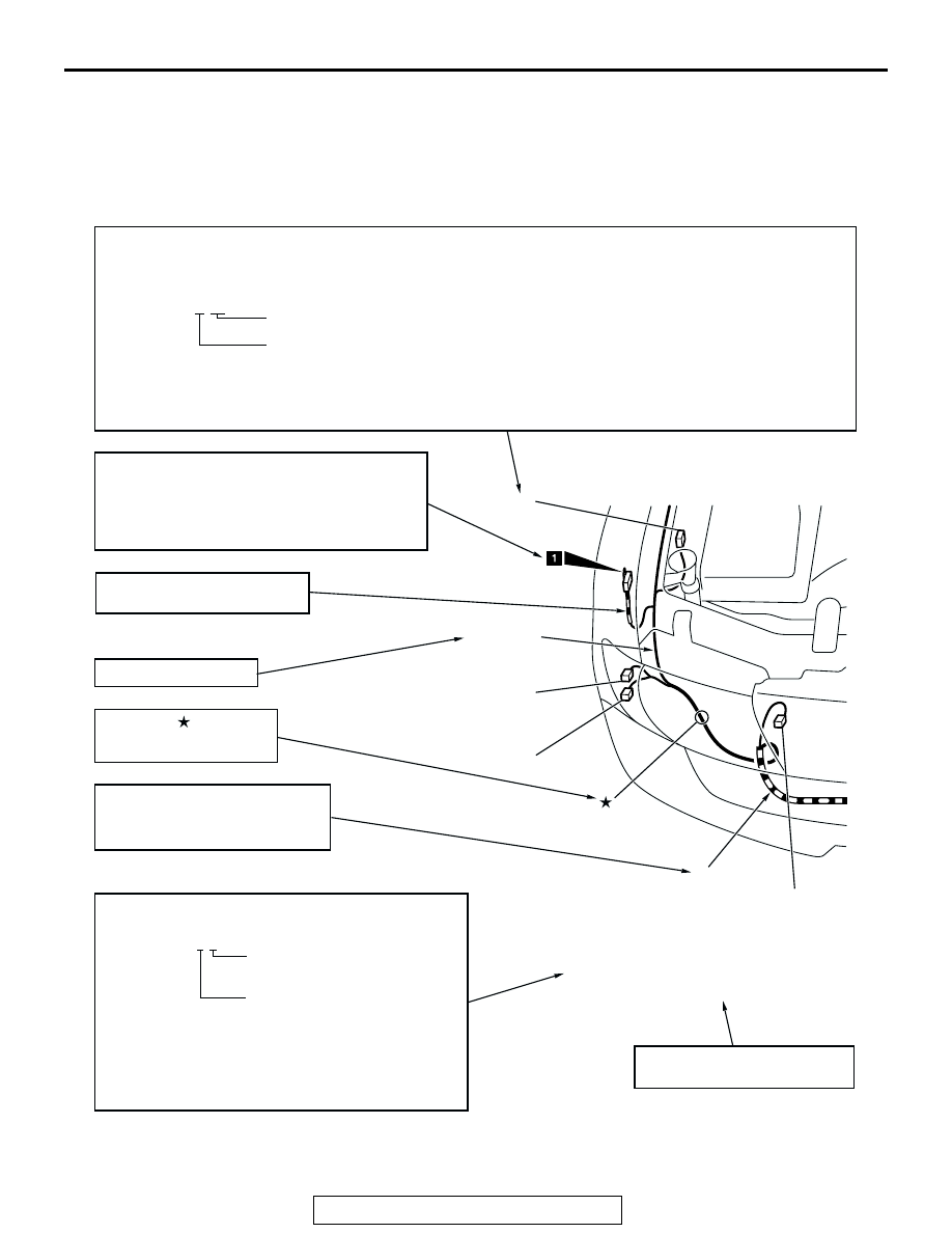
The wiring harness diagrams clearly show the connector locations and harness routines at each site on
actual vehicles. Some variations are included in one configuration diagram. Accordingly, some diagrams may
not be applicable for individual vehicles.
AC303193
A-16
Y
A-17
A-18
A-19
Denotes connector No.
The same connector No. is used throughout the circuit diagrams to facilitate connector location searches.
The first alphabetical symbol indicates the location site of the connector and a number that follows is the unique number.
Numbers are usually assigned to parts in clockwise order on the diagram.
Example: A-19
Number specific to connector (serial number)
Connector location site symbol
A: ENGINE COMPARTMENT
F: FRONT FLOOR AND ROOF
B: ENGINE
G: REAR FLOOR AND UNDER FLOOR
C: TRANSMISSION
H: DOOR
D: DASH PANEL
I: BACK DOOR
E: FLOOR CONSOLE
Denotes ground point.
Same ground number is used throughout circuit
diagrams to facilitate search of ground point.
Refer to GROUP 70 SINGLE PART INSTALLATION
POSITION - GROUND MOUNTING LOCATIONS
for details of ground points.
Denotes the color of the corrugated
tube (If not specified, it is black.)
R: Red
Y: Yellow
A-16 (1) HORN (LOW)
A-17 (3-GR) HEADLIGHT (LOW:RH)
A-18 (2-B) HEADLIGHT (HIGH:RH)
A-19 (2) DUAL PRESSURE SWITCH
Indicates the device to which the
connector is connected.
The mark shows the
standard mounting position
of wiring harness.
AC
Denotes harness name.
FRONT
WIRING
HARNESS
The number of connector pins and the connector color
(except milk white)* are shown for ease of retrieval.
Example: (2-B)
Connector color
(milk white if no color is indicated)
Number of connector pins
*: Typical connector colors
B: Black
BR: Brown
Y: Yellow
V: Violet
L: Blue
O: Orange
G: Green
GR: Gray
R: Red
NONE: Milk white
Denotes a section covered by a
corrugated tube.