Mitsubishi Montero (2002-2004). Manual - part 935
 

  Index      Mitsubishi     Mitsubishi Montero - service repair manual 2002-2004 year


Search            


Content   ..  933  934  935  936   ..


Mitsubishi Montero (2002-2004). Manual - part 935


DIAGNOSTIC TROUBLE CODE PROCEDURES <AUTOMATIC TRANSMISSION>

TSB Revision

DIAGNOSTIC TROUBLE CODE PROCEDURES

23Ac-223

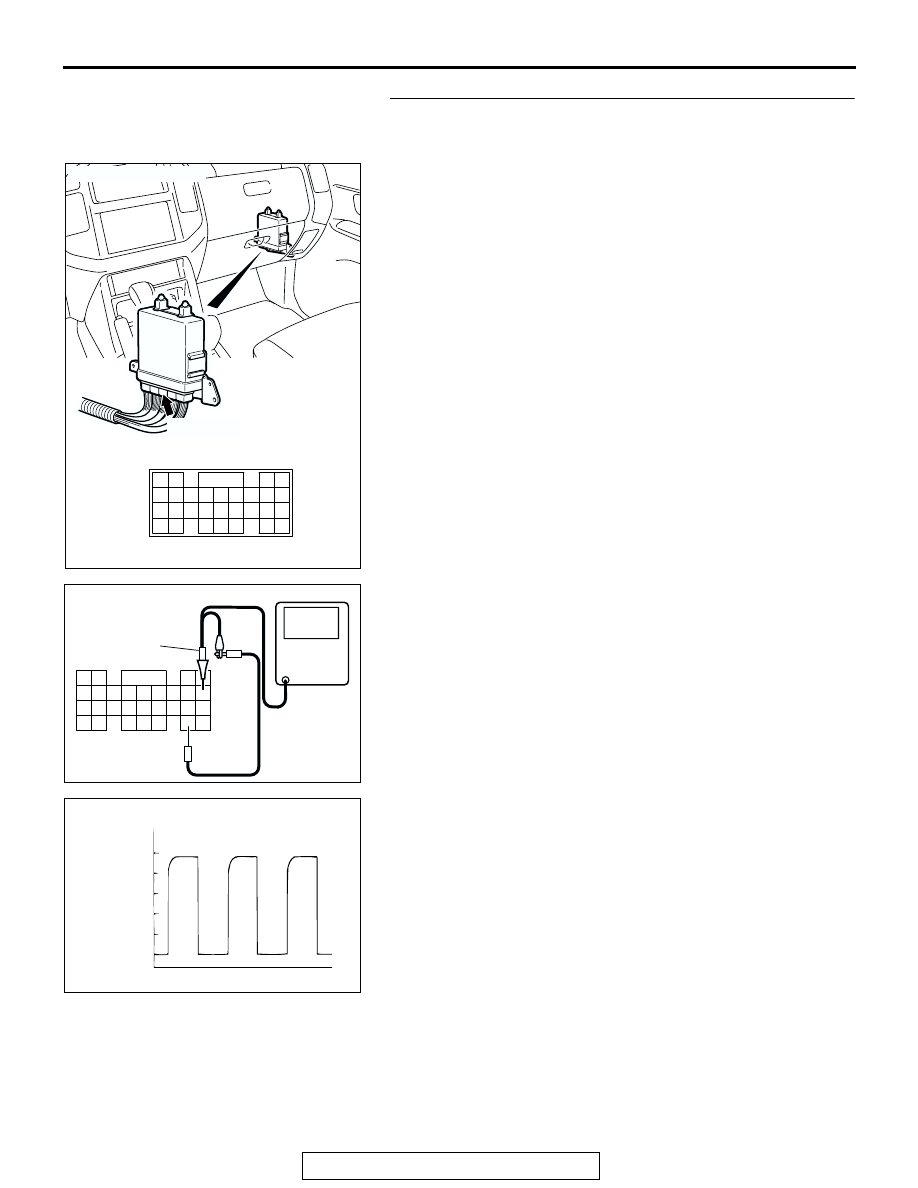
STEP 8. Using an oscilloscope, check the output shaft 
speed sensor waveform at PCM connector D-134 by 
backprobing.
(1) Do not disconnect connector D-134.

(2) Connect an oscilloscope probe to PCM connector D-134 

terminal 73 and terminal 88 by backprobing.

(3) Start the engine and drive the vehicle at a constant speed of 

50 km/h (31 mph). (Gear range: 3rd gear)

(4) Check the output shaft speed sensor waveform.

• The output shaft speed sensor waveform should show a 

pattern similar to the illustration. The maximum value 
should be 4.8 volts and more and the minimum value 
0.8 volt and less. The output waveform should not con-
tain electrical noise.

(5) Turn the ignition switch to the "LOCK" (OFF) position.
Q: Is the waveform normal?

YES : Go to Step 13.
NO :  Go to Step 9.

AC204681AC

CONNECTOR: D-134

D-134 (GR)

61 62

63 64

65 66 67 68 69 70 71 72 73

82

89

81

88

80

79

78

77

87

86

85

76

75

74

84

83

AC204946 AF

OSCILLO-
SCOPE

PROBE

D-134 HARNESS CONNECTOR : 
HARNESS SIDE

76

85

65

72

71

73

82

75

81

74

63 64

66

70

69

68

67

78

87

79

88 89

80

77

86

62

61

83 84

ACX02131AB

NORMAL WAVEFORM

(V)

5

0

DIAGNOSTIC TROUBLE CODE PROCEDURES <AUTOMATIC TRANSMISSION>

TSB Revision

DIAGNOSTIC TROUBLE CODE PROCEDURES

23Ac-224

STEP 9. Check output shaft speed sensor connector C-02, 
PCM connector D-134 and intermediate connector E-114 
for loose, corroded or damaged terminals, or terminals 
pushed back in the connector.
Q: Are the connectors and terminals in good condition?

YES : Go to Step 10.
NO :  Repair or replace the damaged components. Refer to 

GROUP 00E, Harness Connector Inspection 

P.00E-

2

.

AC204746

CONNECTOR : C-02

C-02 (GR)

AB

1 2 3

AC204681AC

CONNECTOR: D-134

D-134 (GR)

61 62

63 64

65 66 67 68 69 70 71 72 73

82

89

81

88

80

79

78

77

87

86

85

76

75

74

84

83

AC204176

CONNECTOR : E-114

BD

38

28

16

33

22

10

31

19

7

1

18

30

29

17

5

6

21

20

32

8

2

9

25

13

3

24

23

3435

1112

27

26

3637

14

4

15

DIAGNOSTIC TROUBLE CODE PROCEDURES <AUTOMATIC TRANSMISSION>

TSB Revision

DIAGNOSTIC TROUBLE CODE PROCEDURES

23Ac-225

STEP 10. Check harness for damage between output shaft 
speed sensor connector C-02 terminal 2 and PCM 
connector D-134 terminal 73.
Q: Is the harness wire in good condition?

YES : Go to Step 11.
NO :  Repair or replace the harness wire.

STEP 11. Replace the output shaft speed sensor.
(1) Replace the output shaft speed sensor. Refer to GROUP 

23B, Transmission 

P.23B-18

.

(2) Test drive the vehicle.
(3) Check for A/T diagnostic trouble code.
Q: Were any A/T DTCs set?

YES : Go to Step 12.
NO :  The procedure is complete.

AC204746

CONNECTOR : C-02

C-02 (GR)

AB

1 2 3

AC204681AC

CONNECTOR: D-134

D-134 (GR)

61 62

63 64

65 66 67 68 69 70 71 72 73

82

89

81

88

80

79

78

77

87

86

85

76

75

74

84

83

ACX01223 AE

OUTPUT SHAFT
SPEED SENSOR

DIAGNOSTIC TROUBLE CODE PROCEDURES <AUTOMATIC TRANSMISSION>

TSB Revision

DIAGNOSTIC TROUBLE CODE PROCEDURES

23Ac-226

STEP 12. Replace the direct planetary carrier.
(1) Replace the direct planetary carrier. Refer to GROUP 23B, 

Transmission 

P.23B-18

.

(2) Test drive the vehicle.
(3) Check for A/T diagnostic trouble code.
Q: Were any A/T DTCs set?

YES : An A/T DTC may have set due to external radio 

frequency interference (RFI) possibly caused by 
cellular phone activity, or aftermarket components 
installed on the vehicle.

NO :  The procedure is complete.

STEP 13. Replace the PCM.
(1) Replace the PCM.
(2) Test drive the vehicle.
(3) Check for A/T diagnostic trouble code.
Q: Were any A/T DTCs set?

YES : Go to Step 14.
NO :  The procedure is complete.

STEP 14. Replace the valve body.
(1) Replace the valve body. Refer to GROUP 23B, 

Transmission 

P.23B-18

.

(2) Test drive the vehicle.
(3) Check for A/T diagnostic trouble code.
Q: Were any A/T DTCs set?

YES : Go to Step 15.
NO :  The procedure is complete.

AC204883

DIRECT 
PLANETARY
CARRIER

AF

ACX02161AD

VALVE BODY ASSEMBLY


Content   ..  933  934  935  936   ..