Mitsubishi Montero (2002-2004). Manual - part 836
 

  Index      Mitsubishi     Mitsubishi Montero - service repair manual 2002-2004 year


Search            


Content   ..  834  835  836  837   ..


Mitsubishi Montero (2002-2004). Manual - part 836


AUTO-CRUISE CONTROL

TSB Revision

ENGINE AND EMISSION CONTROL

17-7

AUTO-CRUISE CONTROL

GENERAL DESCRIPTION

M1172000100225

By using the auto-cruise control, the driver can select 
and maintain a desired cruising speed [approxi-
mately 40 km/h (25 mph) or more] without depress-
ing the accelerator pedal.

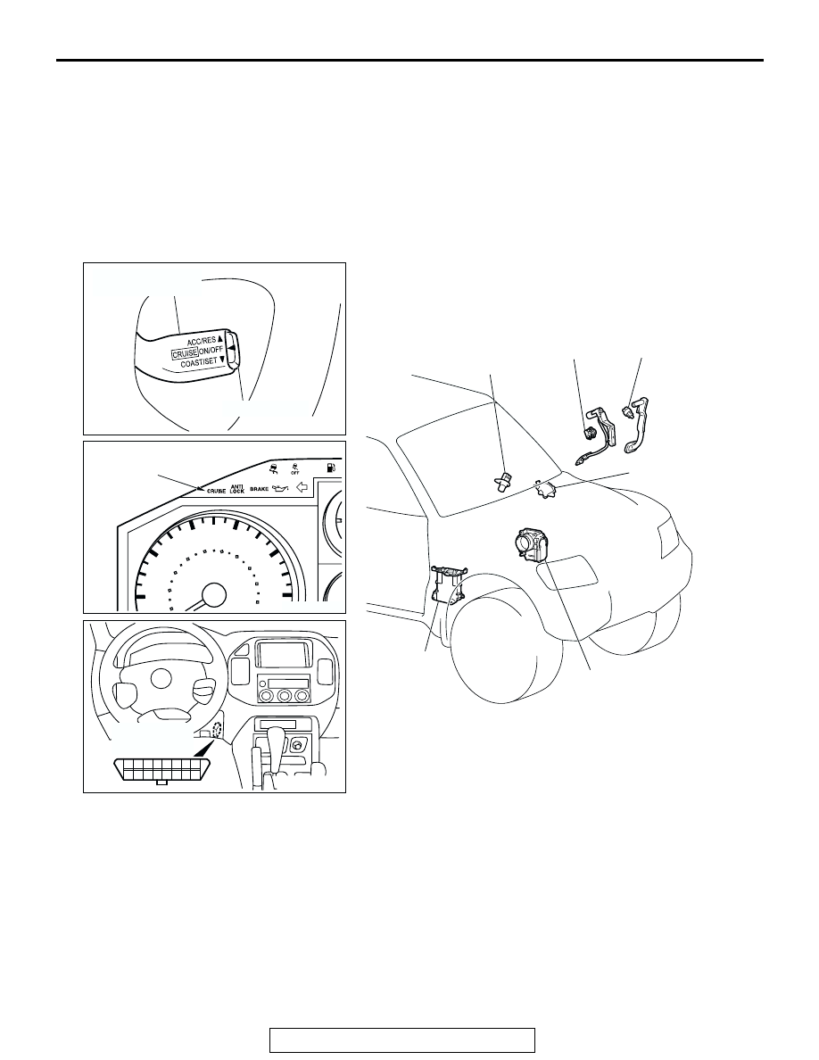
CONSTRUCTION DIAGRAM

AC204216

3

11

1 2

9 10

14

6

5

4

1213

8

7

16

15

AC204217

AC204447

20

20

40

60

80

100 120

140

160

180

200

40

60

80

100

120

km/h

AC204919

AUTO-CRUISE
CONTROL
INDICATOR
LIGHT

ACCELERATOR 
PEDAL
POSITION  
SENSOR

TRANSMISSION
RANGE SWITCH

STOPLIGHT
SWITCH

THROTTLE BODY
ASSEMBLY

POWERTRAIN 
CONTROL 
MODULE (PCM)

AB

VEHICLE 
SPEED
SENSOR

AUTO-CRUISE
CONTROL SWITCH

MAIN SWITCH

DATA LINK
CONNECTOR

AUTO-CRUISE CONTROL

TSB Revision

ENGINE AND EMISSION CONTROL

17-8

SPECIAL TOOLS

M1172000600220

AUTO-CRUISE CONTROL SYSTEM DIAGNOSIS

INTRODUCTION TO AUTO-CRUISE CONTROL SYSTEM DIAGNOSIS

M1172003300217

The auto-cruise control system allows driving without 
stepping on the accelerator pedal by setting a ran-
dom speed between 40 km/h (25 mph) and 200 km/h 
(124 mph). Problems in this system can be investi-
gated by the following methods.

Auto-cruise control system diagnostic 
trouble codes

The auto-cruise control system consists of the 
powertrain control module (PCM), control switches 
and sensors. The control switches and sensors mon-
itor the state of the vehicle. The PCM controls the 
throttle valve opening angle in the throttle body in 

accordance with the input signals from the switches 
and sensors. If the PCM detects a problem on any of 
those components, the PCM estimates where the 
problem may be occurring, and will output a diagnos-
tic trouble code. Diagnostic trouble codes cover the 
auto-cruise control switch, stoplight switch and PCM.

AUTO-CRUISE CONTROL SYSTEM DIAGNOSTIC TROUBLESHOOTING STRATEGY

M1172002000224

Use these steps to plan your diagnostic strategy. If 
you follow them carefully, you will check most of the 

possible causes of an auto-cruise control system 
problem.

TOOL

TOOL NUMBER AND 
NAME

SUPERSESSION

APPLICATION

MB991502 Scan tool 
(MUT-II)

MB991496-OD

Reading diagnostic 
trouble codes

MB991223
A: MB991219
B: MB991220
C: MB991221
D: MB991222
Harness set
A: Inspection harness
B: LED harness
C: LED harness adapter
D: Probe

General service tools

Checking the continuity 
and measuring the 
voltage at the harness 
connector

MB991348
Test harness set

MB991348-01

Checking throttle position 
sensor

B991502

MB991223

A

D

C

B

AD

MB991348

AUTO-CRUISE CONTROL

TSB Revision

ENGINE AND EMISSION CONTROL

17-9

1. Gather information from the customer.
2. Verify that the condition described by the 

customer exists.

3. Check the vehicle for any auto-cruise control 

system DTC.

4. If you can verify the condition but no auto-cruise 

control system DTCs are set, and the malfunction 
may be intermittent. Refer to GROUP 00, How to 
Use Troubleshooting/Inspection Service Points 

− 

How to Cope with Intermittent Malfunctions 

P.00-

6

.

5. If you can verify the condition but there are no 

auto-cruise control system DTCs, or the system 
cannot communicate with scan tool MB991502, 
refer to Symptom Char

P.17-35

 and find the fault.

6. If there is an auto-cruise control system DTC, 

record the number of the code, then erase the 
code from vehicle memory using the scan tool.

7. Re-create the auto-cruise control system DTC set 

conditions to see if the same Auto-cruise Control 
System DTC will set again.

• If the same Auto-cruise Control System DTC sets 

again, perform the diagnostic procedures for the 
set code. Refer to 

P.17-12

, Auto-cruise Control 

System Diagnostic Trouble Code Chart.

AUTO-CRUISE CONTROL SYSTEM DIAGNOSTIC 
TROUBLE CODE DIAGNOSIS

M1172002100210

Retrieving Auto-cruise Control System 
Diagnostic Trouble Codes.

.

Using scan tool MB991502

Required Special Tool:

• MB991502: Scan Tool (MUT-II)

CAUTION

To prevent damage to scan tool MB991502, always turn the 
ignition switch to the "LOCK" (OFF) position before con-
necting or disconnecting scan tool MB991502.
1. Connect scan tool MB991502 to the data link connector.
2. Turn the ignition switch to the "ON" position.
3. Depress the auto-cruise control main switch to illuminate the 

auto-cruise control indicator light in the combination meter.

4. Use scan tool MB991502 to check for auto-cruise control 

system diagnostic trouble codes.

5. Turn the ignition switch to the "LOCK" (OFF) position.
6. Disconnect scan tool MB991502.

.

Using a Auto-cruise Control Indicator Light
1. Turn the ignition switch to the "ON" position while holding 

the auto-cruise control switch in the "SET" position (down). 
Then, within one second, more the cruise control switch up 
to the "RES" position.

2. Read a diagnostic trouble code by observing the flash 

display pattern of the auto-cruise control indicator light in the 
combination meter.

ACX02258AC

MB991502

16-PIN

ACX01172

AB

AUTO-CRUISE
CONTROL
SWITCH

SET
SWITCH: ON

RESUME
SWITCH: ON

AUTO-CRUISE CONTROL

TSB Revision

ENGINE AND EMISSION CONTROL

17-10

DIAGNOSTIC RESULT DISPLAY METHOD WHEN USING THE AUTO-CRUISE 
CONTROL INDICATOR LIGHT

NOTE: Other on-board diagnostic items are also out-
put as voltage waveforms corresponding to diagnos-
tic trouble code numbers.

Erasing Diagnostic Trouble Codes

The diagnostic trouble codes can be erased by the following 
procedure.
NOTE: The diagnostic trouble code will not be erased even if 
the negative battery terminal is disconnected.

.

Using scan tool MB991502

Required Special Tool:

• MB991502: Scan Tool (MUT-II)

CAUTION

To prevent damage to scan tool MB991502, always turn the 
ignition switch to the "LOCK" (OFF) position before con-
necting or disconnecting scan tool MB991502.
1. Connect scan tool MB991502 to the data link connector.
2. Turn the ignition switch to the "ON" position.
3. Use scan tool MB991502 to check for auto-cruise control 

system diagnostic trouble codes.

4. Turn the ignition switch to the "LOCK" (OFF) position.
5. Disconnect scan tool MB991502.

.

WHEN THE DIAGNOSTIC TROUBLE CODE NO.23 IS SET WHEN NO DIAGNOSTIC TROUBLE CODE 

IS SET

AC204251AB

ILLUMINATED

NOT ILLUMINATED

PAUSE
TIME: 3s

1.5s 0.5s

TENS
SIGNAL

PLACE
DIVISION:
2s

UNITS
SIGNAL

0.5s

AC204252

CONTINUOUS ON AND OFF

SIGNALS AT INTERVALS OF 0.5 s

AB

0.5 s

ILLUMINATED

NOT ILLUMINATED

ACX02258AC

MB991502

16-PIN


Content   ..  834  835  836  837   ..