Mitsubishi Montero (2002-2004). Manual - part 832
 

  Index      Mitsubishi     Mitsubishi Montero - service repair manual 2002-2004 year


Search            


Content   ..  830  831  832  833   ..


Mitsubishi Montero (2002-2004). Manual - part 832


TIMING BELT

TSB Revision

ENGINE MECHANICAL

11A-33

TIMING BELT

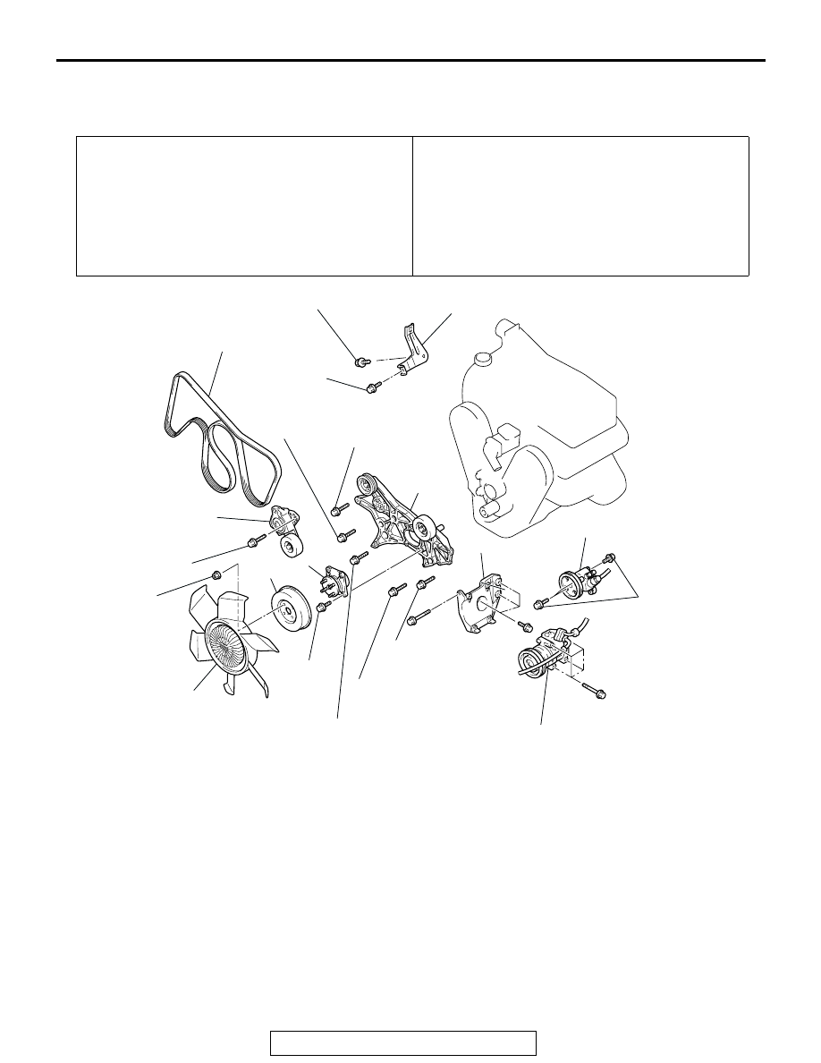
REMOVAL AND INSTALLATION

M1112004300526

Pre-removal Operation
• Skid Plate and Under Cover Removal

• Engine Coolant Draining (Refer to GROUP 14, On-vehicle 

Service 

P.14-5

.)

• Battery and Battery Tray Removal

• Air Cleaner Removal (Refer to GROUP 15, Air Cleaner 

P.15-6

.)

• Radiator Shroud Cover Removal (Refer to GROUP 14, 

Radiator 

P.14-8

.)

Post-installation Operation
• Radiator Shroud Cover Installation (Refer to GROUP 14, 

Radiator 

P.14-8

.)

• Air Cleaner Installation (Refer to GROUP 15, Air Cleaner 

P.15-6

.)

• Battery and Battery Tray Installation

• Engine Coolant Refilling (Refer to GROUP 14, On-vehicle 

Servic

P.14-5

.)

• Skid Plate and Under Cover Installation

AC204211 

AB

24 ± 4 N·m
18 ± 3 ft-lb

41 ± 8 N·m
30 ± 6 ft-lb

74 ± 9 N·m
54 ± 7 ft-lb

44 ± 10 N·m
33 ± 7 ft-lb

11 ± 1 N·m
98 ± 8 in-lb

49 ± 9 N·m
36 ± 7 ft-lb

24 ± 4 N·m
18 ± 3 ft-lb

41 ± 8 N·m
30 ± 6 ft-lb

1

5

6

7

8

10

3

23 ± 3 N·m
17 ± 2 ft-lb

4

9

2

22 ± 4 N·m
16 ± 3 ft-lb

49 ± 5 N·m
36 ± 4 ft-lb

REMOVAL STEPS

1.

DRIVE BELT

2.

COOLING FAN

3.

COOLING FAN PULLEY

<<A>>

>>E<<

4.

DRIVE BELT AUTO TENSIONER

5.

ACCESSORY MOUNT STAY

<<B>>

6.

POWER STEERING OIL PUMP 
ASSEMBLY

<<B>>

7.

A/C COMPRESSOR ASSEMBLY

8.

COMPRESSOR BRACKET

9.

COOLING FAN BRACKET 
ASSEMBLY

>>D<<

10. ACCESSORY MOUNT 

ASSEMBLY

REMOVAL STEPS (Continued)

TIMING BELT

TSB Revision

ENGINE MECHANICAL

11A-34

Required Special Tools:
MB991800: Pulley Holder
MD991802: Pin B

MD998767: Tension Pulley Socket Wrench
MD998769: Crankshaft Pulley Spacer

REMOVAL SERVICE POINTS

.

<<A>> DRIVE BELT AUTO TENSIONER REMOVAL
The following operations will be needed due to the introduction 
of the serpentine drive system with the drive belt auto ten-
sioner.

AC204108

14 ± 1 N·m
120 ± 13 in-lb

44 ± 10 N·m
33 ± 7 ft-lb

185 ± 5 N·m
137 ± 3 ft-lb

(ENGINE OIL)

11 ± 1 N·m
96 ± 8 in-lb

11 ± 1 N·m
98 ± 8 in-lb

11 ± 1 N·m
96 ± 8 in-lb

48 ± 6 N·m
36 ± 4 ft-lb

23 ± 3 N·m
17 ± 2 ft-lb

11

15

18

20

14

16

17

13

12

44 ± 5 N·m
33 ± 3 ft-lb

AB

19

REMOVAL STEPS

11. TIMING BELT UPPER COVER 

ASSEMBLY

<<C>>

>>C<<

12. CRANKSHAFT PULLEY
13. TIMING BELT INDICATOR 

BRACKET

14. TIMING BELT LOWER COVER 

ASSEMBLY

>>B<<

15. AUTO-TENSIONER

<<D>>

>>A<<

16. TIMING BELT
17. TENSION PULLEY
18. TENSIONER ARM ASSEMBLY
19. SHAFT
20. IDLER PULLEY

REMOVAL STEPS (Continued)

TIMING BELT

TSB Revision

ENGINE MECHANICAL

11A-35

1. Insert a 12.7 mm (1/2 inch) breaker bar into the square hole 

on the drive belt auto tensioner, and rotate it clockwise until 
the tensioner touches the stopper. 

2. Align hole B with hole A, and insert a 5.0 mm (0.20 inch) 

Allen wrench to hold the tensioner. Then loosen the drive 
belt, and then remove the drive belt auto tensioner. 

.

<<B>> POWER STEERING OIL PUMP ASSEMBLY / A/C 
COMPRESSOR ASSEMBLY REMOVAL
1. Do not disconnect the hoses to remove the pump and 

compressor.

2. Support the removed pump and compressor with a wire, etc. 

so that they will not get in the way while working.

.

<<C>> CRANKSHAFT PULLEY REMOVAL
Use special tools MB991800 and MB991802 to remove the 
crankshaft pulley from the crankshaft.

.

ACX01424AB

HOLE A

HOLE B

SQUARE 

HOLE

CLOCKWISE

ALLEN WRENCH

ACX01675AB

MB991800

MB991802

TIMING BELT

TSB Revision

ENGINE MECHANICAL

11A-36

<<D>> TIMING BELT REMOVAL

CAUTION

Never turn the crankshaft counterclockwise.
1. Turn the crankshaft clockwise to align each timing mark and 

to set the number 1 cylinder to compression top dead center.

2. If the timing belt is to be reused, chalk mark the flat side of 

the belt with an arrow indicating the clockwise direction.

3. Loosen the center bolt of the tension pulley, and then 

remove the timing belt.

INSTALLATION SERVICE POINTS

.

>>A<< TIMING BELT INSTALLATION
1. Align the timing marks of the camshaft sprocket with those 

of crankshaft sprocket.

CAUTION

The camshaft sprocket (right bank) can turn easily due to 
the spring force applied, so be careful not to get your fin-
gers caught.
2. Install the timing belt by the following procedure so that 

there is no deflection in the timing belt between each 
sprocket and pulley.

(1) Crankshaft sprocket
(2) Idler pulley
(3) Camshaft sprocket (Left bank)
(4) Water pump pulley
(5) Camshaft sprocket (Right bank)
(6) Tension pulley

ACX00537

TIMING 
MARK

TIMING 
MARK

TIMING 
MARK

CAMSHAFT 
SPROCKET 
(RIGHT BANK)

CAMSHAFT 
SPROCKET 
(LEFT BANK)

CRANKSHAFT 
SPROCKET

TENSION 
PULLEY

AB

CENTER 
BOLT


Content   ..  830  831  832  833   ..