Mitsubishi Montero (2002-2004). Manual - part 775
 

  Index      Mitsubishi     Mitsubishi Montero - service repair manual 2002-2004 year


Search            


Content   ..  773  774  775  776   ..


Mitsubishi Montero (2002-2004). Manual - part 775


AIR BAG MODULE(S) AND CLOCK SPRING

TSB Revision

SUPPLEMENTAL RESTRAINT SYSTEM (SRS)

52Ba-33

>>C<< POST-INSTALLATION INSPECTION 
1. Reconnect the negative (-) battery cable. 
2. Turn the ignition key to the "ON" position. 
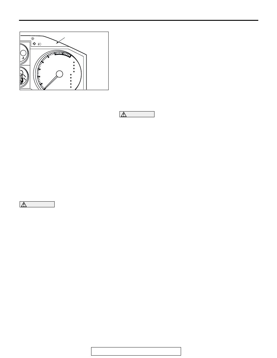
3. Does the "SRS" warning light illuminate for approximately 

seven seconds after turning "OFF?" 

4. If yes, the SRS system is functioning properly.

If no, refer to page 

P.52Bb-3

INSPECTION

M1524002200131

WARNING

If a dent, crack, deformation or rust is discovered, 
replace the SRS-ECU with a new one. 

• Check the SRS-ECU and brackets for dents, cracks or 

deformation. 

• Check the SRS-ECU connector for damage, and the termi-

nals for deformation. 

NOTE: Refer to for inspection of SRS-ECU for other than phys-
ical damage. 

AIR BAG MODULE(S) AND CLOCK SPRING

REMOVAL AND INSTALLATION 

M1524002400328

WARNING

Never attempt to disassemble or repair the air bag modules or clock spring. If faulty, 
replace it. 

Do not drop the air bag modules or clock spring or allow contact with water, grease or oil.

Replace it if a dent, crack, deformation or rust is detected.

The air bag modules should be stored on a flat surface and placed so that the pad surface 
is facing upward. Do not place anything on top of it. 

Do not expose the air bag modules to temperatures over 93

°C(200 °F). 

After deployment of an air bag, replace the air bag modules. Check the clock spring and if 
faulty, replace it with a new part. 

Wear gloves and safety glasses when handling air bags that have already deployed. 

An undeployed air bag module should only be disposed of in accordance with the proce-
dures described on 

P.52Ba-48

<Side-airbag module>

For removal and installation of the front seatback assembly with side-airbag module, refer to GROUP 52A, 
Front seat 

P.52A-13

.

ACX01667

AT

TEMP

SRS

P
R
N
D

5
4
3
2
1

x1000r/min

2

3

4

5

6

7

8

1

AC

SRS WARNING LIGHT

AIR BAG MODULE(S) AND CLOCK SPRING

TSB Revision

SUPPLEMENTAL RESTRAINT SYSTEM (SRS)

52Ba-34

<Air bag module (driver's side) and clock spring>

Pre-removal Operation
• After setting the steering wheel and the front wheels to the 

straight ahead position, remove the ignition key. 

AC204150

AC204150

6

4

3

3.9 ± 0.4 N·m
35 ± 3.5 in-lb

3.9 ± 0.4 N·m
35 ± 3.5 in-lb

0.69 ± 0.15 N·m
6.1 ± 1.3 in-lb

5

A

A

B

B

AB

50 ± 5 N·m
37 ± 4 ft-lb

1

2

COLUMN 
SWITCH

6

4

STUD

2

STUD

4

STUD

STUD

SECTION A - A

SECTION B - B

SECTION C - C

SECTION D - D

C

C

D

D

NOTE
          :STUD POSITION

2

7

AIR BAG MODULE REMOVAL 
STEPS

<<A>>

1.

NEGATIVE (-) BATTERY CABLE 
CONNECTION

<<B>>

2.

COVER

<<C>>

3.

STEERING WHEEL AND AIR 
BAG MODULE

4.

STEERING WHEEL

<<D>>

5.

AIR BAG MODULE
CLOCK SPRING REMOVAL 
STEPS

<<A>>

1.

NEGATIVE (-) BATTERY CABLE 
CONNECTION

<<B>>

2.

COVER

<<C>>

3.

STEERING WHEEL AND AIR 
BAG MODULE

COLUMN COVER LOWER

<<E>>

6.

CLOCK SPRING

7.

CLOCK SPRING SUB HARNESS
AIR BAG MODULE 
INSTALLATION STEPS

>>A<<

PRE-INSTALLATION 
INSPECTION

5.

AIR BAG MODULE

4.

STEERING WHEEL

>>C<<

3.

STEERING WHEEL AND AIR 
BAG MODULE

2.

COVER

CLOCK SPRING REMOVAL 
STEPS (Continued)

AIR BAG MODULE(S) AND CLOCK SPRING

TSB Revision

SUPPLEMENTAL RESTRAINT SYSTEM (SRS)

52Ba-35

Required Special Tools: 

• MB990784: Ornament Remover 

• MB991223 (MB991222): Harness Set (Probe)

• MB991502: Scan Tool (MUT-II)

<Air bag module (front passenger's side)>

1.

NEGATIVE (-) BATTERY CABLE 
CONNECTION

>>D<<

POST-INSTALLATION 
INSPECTION
CLOCK SPRING 
INSTALLATION STEPS

>>A<<

PRE-INSTALLATION 
INSPECTION

7.

CLOCK SPRING SUB HARNESS

>>B<<

6.

CLOCK SPRING

COLUMN COVER LOWER

>>C<<

3.

STEERING WHEEL AND AIR 
BAG MODULE

2.

COVER

1.

NEGATIVE (-) BATTERY CABLE 
CONNECTION

>>D<<

POST-INSTALLATION 
INSPECTION

AIR BAG MODULE 
INSTALLATION STEPS 

ACX01488

ACX00583

1

2

AB

3

AIR BAG MODEL REMOVAL 
STEPS

<<A>>

1.

NEGATIVE (-) BATTERY CABLE 
CONNECTION

GLOVE BOX, UPPER (REFER TO 
GROUP 52A, INTERIOR 

P.52A-2

.) 

GLOVE BOX (REFER TO GROUP 
52A, INTERIOR 

P.52A-2

.)

<<F>>

2.

AIR BAG SIDE PLATE

<<G>>

3.

AIR BAG MODULE

AIR BAG MODULE 
INSTALLATION STEPS

>>A<<

PRE-INSTALLATION INSPECTION

3.

AIR BAG MODULE 

2.

AIR BAG SIDE PLATE

GLOVE BOX (REFER TO GROUP 
52A, INTERIOR 

P.52A-2

.)

GLOVE BOX, UPPER (REFER TO 
GROUP 52A, INTERIOR 

P.52A-2

.) 

1.

NEGATIVE BATTERY CABLE 
CONNECTION

>>D<<

POST-INSTALLATION 
INSPECTION

AIR BAG MODULE(S) AND CLOCK SPRING

TSB Revision

SUPPLEMENTAL RESTRAINT SYSTEM (SRS)

52Ba-36

Required Special Tool:
MB991502:Scan Tool (MUT-II) 

REMOVAL SERVICE POINTS

.

<<A>> NEGATIVE (-) BATTERY CABLE DISCONNECTION

DANGER

Wait at least 60 seconds after disconnecting the bat-
tery cable before doing any further work. (Refer to 

P.52Ba-18

.)

WARNING

Battery posts, terminals and related accessories con-
tain lead and lead compounds. WASH HANDS AFTER 
HANDLING.

Disconnect the negative (-) battery cable from the battery and 
tape the terminal to prevent accidental connection and air 
bag(s) deployment.

.

<<B>> COVER REMOVAL 
Insert the special tool from the position as shown by the arrow 
in the illustration to remove the cover.
NOTE: There is a cutout for tool insertion at the inside of posi-
tion shown in the illustration.

.

<<C>> STEERING WHEEL AIR BAG MODULE ASSEMBLY 
REMOVAL
1. Remove the air bag module and the horn switch connector 

through the hole appeared after removing the steering wheel 
cover.

ACX00583

INSULATING TAPE

BATTERY

BATTERY CABLE (–)

AC

ACX00600 AB

MB990784

AC100441AE

D-229 AIR BAG MODULE
CONNECTOR

STEERING WHEEL

A


Content   ..  773  774  775  776   ..