Mitsubishi Montero (2002-2004). Manual - part 731
 

  Index      Mitsubishi     Mitsubishi Montero - service repair manual 2002-2004 year


Search            


Content   ..  729  730  731  732   ..


Mitsubishi Montero (2002-2004). Manual - part 731


TSB Revision

DIAGNOSTIC TROUBLE CODE PROCEDURES

13Ac-621

DIAGNOSIS

Required Special Tool:

• MB991502: Scan Tool (MUT-II)

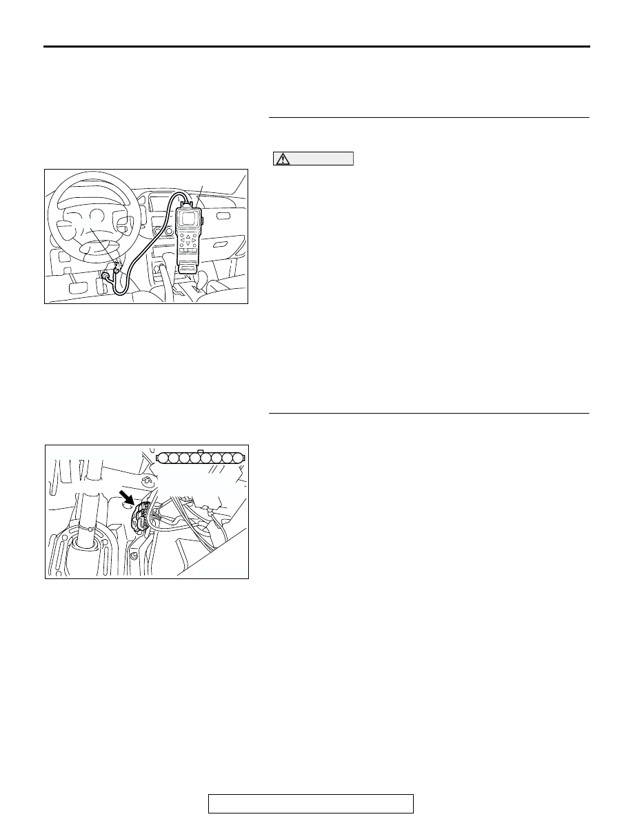
STEP 1. Using scan tool MB991502, check data list item 77: 
Accelerator Pedal Position Sensor (sub).

CAUTION

To prevent damage to scan tool MB991502, always turn the 
ignition switch to the "LOCK"(OFF) position before con-
necting or disconnecting scan tool MB991502.
(1) Connect scan tool MB991502 to the data link connector.
(2) Turn the ignition switch to the "ON" position.
(3) Set scan tool MB991502 to the data reading mode for   item 

77, Accelerator Pedal Position Sensor (sub).

• Output voltage is between 0.905 and 1.165 volts when 

foot is released from accelerator pedal.

• Output voltage is 4.035 volts or higher when accelerator 

pedal is fully depressed.

(4) Turn the ignition switch to the "LOCK"(OFF) position.
Q: Is the sensor operating properly?

YES : It can be assumed that this malfunction is intermittent.      

Refer to GROUP 00, How to Use Troubleshooting/
Inspection Service Points 

P.00-6

.

NO :  Go to Step 2.

STEP 2. Check connector D-138 at accelerator pedal 
position sensor for damage.
Q: Is the connector in good condition?

YES : Go to Step 3.
NO :  Repair or replace it. Refer to GROUP 00E, Harness 

Connector Inspection 

P.00E-2

. Then go to Step 12.

ACX01539

16-PIN

MB991502

AC

AK200945

3

4

5

1

2

8

6

7

AB

CONNECTOR: D-138

HARNESS 
CONNECTOR: 
COMPONENT SIDE

D-138(GR)

TSB Revision

DIAGNOSTIC TROUBLE CODE PROCEDURES

13Ac-622

STEP 3. Check the accelerator pedal position sensor.
(1) Disconnect the accelerator pedal position sensor connector 

D-138.

(2) Measure resistance between terminal No. 1 and No. 2 and 

between terminal No. 7 and No. 8.

Standard value: 3.5 

 6.5 kiloohms

(3) Measure resistance between terminal No. 2 and No. 3 and 

between terminal No. 6 and No. 8.

(4) Move the accelerator pedal from the idle position to the full-

open position.

• Resistance value changes in accordance with the accel-

erator pedal depression smoothly.

Q: Is the resistance normal?

YES : Go to Step 4.
NO :  Replace the accelerator pedal position sensor. Then 

go to Step 12.

AK200945

3

4

5

1

2

8

6

7

AB

CONNECTOR: D-138

HARNESS 
CONNECTOR: 
COMPONENT SIDE

D-138(GR)

6 7 8

1 2 3 4 5

AK201450

ACCELERATOR PEDAL
POSITION SENSOR
SIDE CONNECTOR

AB

6 7 8

1 2 3 4 5

AK201451

ACCELERATOR PEDAL
POSITION SENSOR
SIDE CONNECTOR

AB

TSB Revision

DIAGNOSTIC TROUBLE CODE PROCEDURES

13Ac-623

STEP 4. Measure the sensor supply voltage at accelerator 
pedal position sensor harness side connector D-138.
(1) Disconnect the connector D-138 and measure at the 

harness side.

(2) Turn the ignition switch to the "ON" position.

(3) Measure the voltage between terminal No. 8 and ground.

• Voltage should be between 4.8 and 5.2 volts.

(4) Turn the ignition switch to the "LOCK"(OFF) position.
Q: Is the measured voltage between 4.8 and 5.2 volts?

YES : Go to Step 8.
NO :   Go to Step 5.

STEP 5. Check connector D-135 at PCM for damage.
Q: Is the connector in good condition?

YES : Go to Step 6.
NO :  Repair or replace it. Refer to GROUP 00E, Harness 

Connector Inspection 

P.00E-2

. Then go to Step 12.

AK200945

3

4

5

1

2

8

6

7

AB

CONNECTOR: D-138

HARNESS 
CONNECTOR: 
COMPONENT SIDE

D-138(GR)

3

4

5

1

2

8

6

7

AK201456

D-138 HARNESS 
CONNECTOR: 
COMPONENT SIDE

AB

AK200947

91

92

93

94

95

96

97

98

99

100

101

102

103

104

105

106

107

108

109

110

111

112

113

114

115

116

117

118

119

120

CONNECTOR: D-135

HARNESS CONNECTOR: 
COMPONENT SIDE

AB

PCM

D-135(GR)

TSB Revision

DIAGNOSTIC TROUBLE CODE PROCEDURES

13Ac-624

STEP 6. Check for open circuit and short circuit to ground 
between accelerator pedal position sensor connector D-
138 (terminal No. 8) and PCM connector D-135 (terminal 
No. 97).
Q: Is the harness wire in good condition?

YES : Go to Step 7.
NO :  Repair it. Then go to Step 12.

STEP 7. Using scan tool MB991502, check data list item 77: 
Accelerator Pedal Position Sensor (sub).

CAUTION

To prevent damage to scan tool MB991502, always turn the 
ignition switch to the "LOCK"(OFF) position before con-
necting or disconnecting scan tool MB991502.
(1) Connect scan tool MB991502 to the data link connector.
(2) Turn the ignition switch to the "ON" position.
(3) Set scan tool MB991502 to the data reading mode for item 

77, Accelerator Pedal Position Sensor (sub).

• Output voltage is between 0.905 and 1.165 volts when 

foot is released from accelerator pedal.

• Output voltage is 4.035 volts or higher when accelerator 

pedal is fully depressed.

(4) Turn the ignition switch to the "LOCK"(OFF) position.
Q: Is the sensor operating properly?

YES : It can be assumed that this malfunction is intermittent. 

Refer to GROUP 00, How to Use Troubleshooting/
Inspection  Service Points 

P.00-6

.

NO :  Replace the PCM. Then go to Step 12.

AK200945

3

4

5

1

2

8

6

7

AB

CONNECTOR: D-138

HARNESS 
CONNECTOR: 
COMPONENT SIDE

D-138(GR)

AK200947

91

92

93

94

95

96

97

98

99

100

101

102

103

104

105

106

107

108

109

110

111

112

113

114

115

116

117

118

119

120

CONNECTOR: D-135

HARNESS CONNECTOR: 
COMPONENT SIDE

AB

PCM

D-135(GR)

ACX01539

16-PIN

MB991502

AC


Content   ..  729  730  731  732   ..