Mitsubishi Montero (2002-2004). Manual - part 704
 

  Index      Mitsubishi     Mitsubishi Montero - service repair manual 2002-2004 year


Search            


Content   ..  702  703  704  705   ..


Mitsubishi Montero (2002-2004). Manual - part 704


TSB Revision

DIAGNOSTIC TROUBLE CODE PROCEDURES

13Ac-513

DIAGNOSIS

Required Special Tool:

• MB991502: Scan Tool (MUT-II)

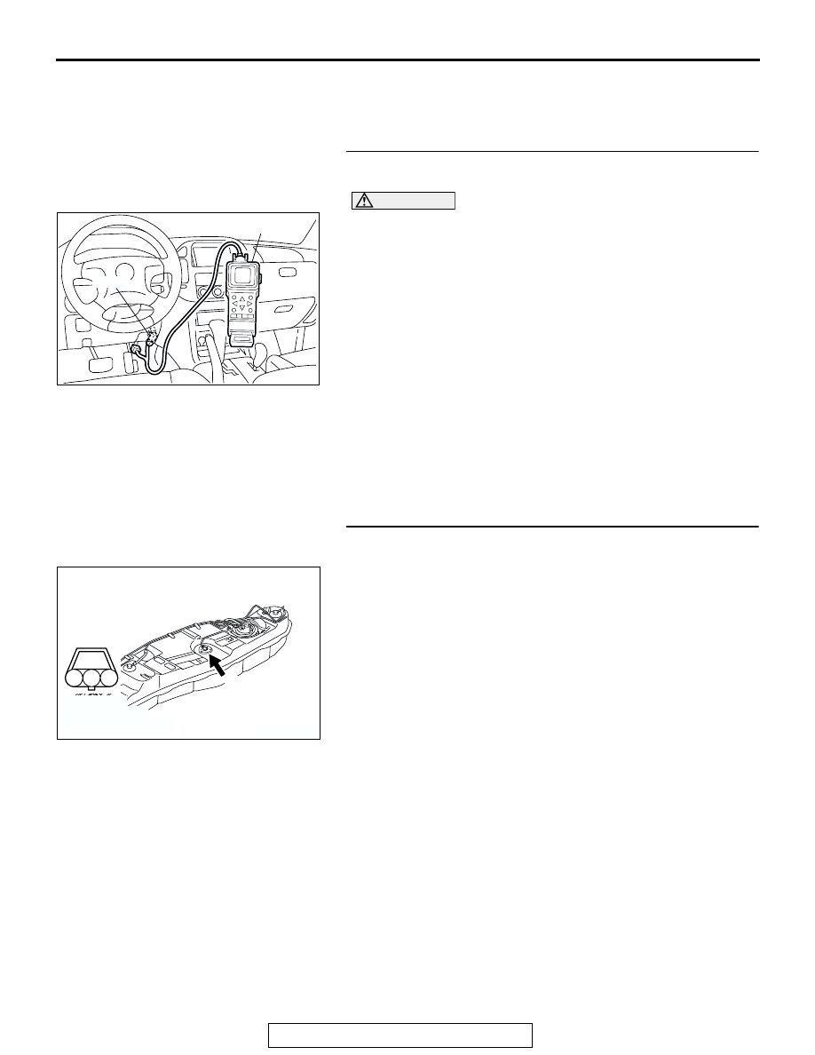
STEP 1. Using scan tool MB991502, check data list item 
4B: Fuel Level Sensor.

CAUTION

To prevent damage to scan tool MB991502, always turn the 
ignition switch to the "LOCK" (OFF) position before con-
necting or disconnecting scan tool MB991502.
(1) Connect scan tool MB991502 to the data link connector.
(2) Turn the ignition switch to the "ON" position.
(3) Set scan tool MB991502 to the data reading mode for item 

4B, Fuel Level Sensor.

• When the fuel gauge is near "FULL", voltage should be 

100 

− 3,600 mV.

• When the fuel gauge is near "EMPTY", voltage should 

be 2,700 

− 6,200 mV.

(4) Turn the ignition switch to the "LOCK" (OFF) position.
Q: Is the sensor operating properly?

YES : It can be assumed that this malfunction is intermittent. 

Refer to GROUP 00, How to Use Troubleshooting/
Inspection Service Points 

P.00-6

.

NO :  Go to Step 2.

STEP 2. Check connector G-03 at the fuel level sensor for 
damage.
Q: Is the connector in good condition?

YES : Go to Step 3.
NO :  Repair or replace it. Refer to GROUP 00E, Harness 

Connector Inspection 

P.00E-2

. Then go to Step 12.

ACX01539

16-PIN

MB991502

AC

AK200959

1

2

3

AB

CONNECTOR: G-03

G-03(B)

HARNESS 
CONNECTOR: 
COMPONENT SIDE

TSB Revision

DIAGNOSTIC TROUBLE CODE PROCEDURES

13Ac-514

STEP 3. Check the continuity at fuel level sensor harness 
side connector G-03.
(1) Disconnect the connector G-03 and measure at the harness 

side.

(2) Check for the continuity between terminal No. 2 and 

ground.

• Should be less than 2 ohms.

Q: Is the continuity normal?

YES : Go to Step 4.
NO :  Check connector F-07 at intermediate connector for 

damage, and repair or replace as required. Refer to 
GROUP 00E, Harness Connector Inspection 

P.00E-

2

. If intermediate connector is in good condition, 

repair harness wire between fuel level sensor 
connector G-03 (terminal No. 2) and ground because 
of open circuit or harness damage. Then go to Step 
12.

STEP 4. Measure the sensor supply voltage at fuel level 
sensor harness side connector G-03.
(1) Disconnect the connector G-03 and measure at the harness 

side.

(2) Disconnect the combination connector D-03.
(3) Turn the ignition switch to the "ON" position.

(4) Measure the voltage between terminal No. 1 and ground.

• Voltage should be battery positive voltage.

(5) Turn the ignition switch to the "LOCK" (OFF) position.
Q: Is battery positive voltage (approximately 12 volts) 

present?
YES : 
Go to Step 9.
NO :  Go to Step 5.

AK200959

1

2

3

AB

CONNECTOR: G-03

G-03(B)

HARNESS 
CONNECTOR: 
COMPONENT SIDE

AK101071

3 2 1

G-03 HARNESS 
CONNECTOR: 
COMPONENT SIDE

AF

AK200959

1

2

3

AB

CONNECTOR: G-03

G-03(B)

HARNESS 
CONNECTOR: 
COMPONENT SIDE

AK101097

3 2 1

AD

G-03 HHARNESS 
CONNECTOR: 
COMPONENT SIDE

TSB Revision

DIAGNOSTIC TROUBLE CODE PROCEDURES

13Ac-515

STEP 5. Measure the sensor supply voltage at PCM 
connector D-134 by backprobing.
(1) Do not disconnect the PCM connector D-134.
(2) Disconnect the combination meter connector D-03.
(3) Turn the ignition switch to the "ON" position.

(4) Measure the voltage between terminal No. 72 and ground 

by backprobing.

• When the fuel gauge is near "FULL", voltage should be 

0.1 and 3.6 volts.

• When the fuel gauge is near "EMPTY", voltage should 

be 2.7 and 6.2 volts.

(5) Turn the ignition switch to the "LOCK" (OFF) position.
Q: Is the voltage normal?

YES : Go to Step 6.
NO :  Go to Step 7.

STEP 6. Check connector D-134 at PCM for damage.
Q: Is the connector in good condition?

YES :  Check connector D-111, E-113 and F-07 at 

intermediate connector for damage, and repair or 
replace as required. Refer to GROUP 00E, Harness 
Connector Inspection 

P.00E-2

. If intermediate 

connector are in good condition, repair harness wire 
between fuel level sensor connector G-03 (terminal 
No. 1) and PCM connector D-134 (terminal No. 72) 
because of open circuit. Then go to Step 12.

NO :  Repair or replace it. Refer to GROUP 00E, Harness 

Connector Inspection 

P.00E-2

. Then go to Step 12.

AK201166

61

62

63

64

65

66

67

68

69

70

71

76

77

78

79

85

86

87

80

72

73

74

75

81

82

83

84

88

89

CONNECTOR: D-134

AB

PCM

D-134(GR)

HARNESS CONNECTOR: 
COMPONENT SIDE

AK201423

61
656667686970 717273
74757677787980 8182
8384

858687

8889

62

6364

D-134 HARNESS 
CONNECTOR: 
HARNESS SIDE

AB

AK201166

61

62

63

64

65

66

67

68

69

70

71

76

77

78

79

85

86

87

80

72

73

74

75

81

82

83

84

88

89

CONNECTOR: D-134

AB

PCM

D-134(GR)

HARNESS CONNECTOR: 
COMPONENT SIDE

TSB Revision

DIAGNOSTIC TROUBLE CODE PROCEDURES

13Ac-516

STEP 7. Check connector D-134 at PCM for damage.
Q: Is the connector in good condition?

YES : Go to Step 8.
NO :  Repair or replace it. Refer to GROUP 00E, Harness 

Connector Inspection 

P.00E-2

. Then go to Step 12.

STEP 8. Check for short circuit to ground between fuel 
level sensor connector G-03 (terminal No. 1) and PCM 
connector D-134 (terminal No. 72).
Q: Is the harness wire in good condition?

YES : Replace the PCM. Then go to Step 12.
NO :  Repair it. Then go to Step 12.

STEP 9. Check the fuel level sensor.
Refer to GROUP 54, Combination Meter. 

P.54A-63

Q: Is the fuel level sensor normal?

YES : Go to Step 10.
NO :  Replace the fuel level sensor. Then go to Step 12.

AK201166

61

62

63

64

65

66

67

68

69

70

71

76

77

78

79

85

86

87

80

72

73

74

75

81

82

83

84

88

89

CONNECTOR: D-134

AB

PCM

D-134(GR)

HARNESS CONNECTOR: 
COMPONENT SIDE

AK200959

1

2

3

AB

CONNECTOR: G-03

G-03(B)

HARNESS 
CONNECTOR: 
COMPONENT SIDE

AK201166

61

62

63

64

65

66

67

68

69

70

71

76

77

78

79

85

86

87

80

72

73

74

75

81

82

83

84

88

89

CONNECTOR: D-134

AB

PCM

D-134(GR)

HARNESS CONNECTOR: 
COMPONENT SIDE


Content   ..  702  703  704  705   ..