Mitsubishi Montero (2002-2004). Manual - part 487
 

  Index      Mitsubishi     Mitsubishi Montero - service repair manual 2002-2004 year


Search            


Content   ..  485  486  487  488   ..


Mitsubishi Montero (2002-2004). Manual - part 487


RADIO WITH TAPE PLAYER AND CD PLAYER

TSB Revision

CHASSIS ELECTRICAL

54A-119

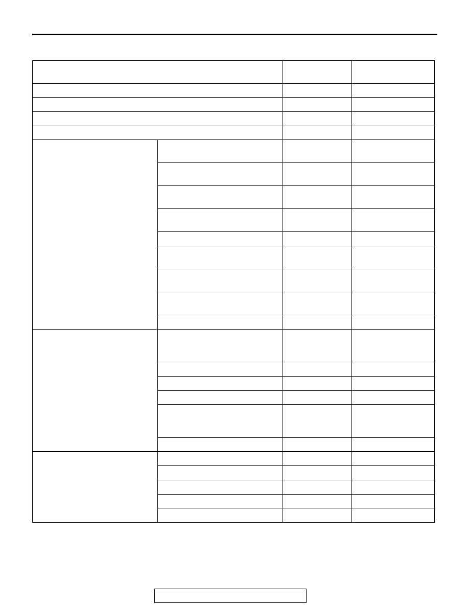
TROUBLE SYMPTOM CHART

M1544004900321

SYMPTOMS

INSPECTION 
PROCEDURE

REFERENCE PAGE

When power switch is turned "ON," no power is available

1

P.54A-120

No sound. <vehicles with amplifier>

2

P.54A-125

No sound from one speaker. <vehicles without amplifier>

3

P.54A-130

No sound from one speaker. <vehicles with amplifier>

4

P.54A-149

Noise

Noise is present while moving 
(AM).

5

P.54A-165

Noise is present while moving 
(FM).

6

P.54A-166

Sound mixed with noise, only at 
night (AM).

7

P.54A-167

Noise is overpowering both AM 
and FM.

8

P.54A-167

Excessive noise on AM and FM. 9

P.54A-168

Noise is detected with engine 
running.

10

P.54A-169

Noise Appears during vibration 
or shocks.

11

P.54A-170

Noise sometimes appears on 
FM during traveling.

12

P.54A-172

Constant noise.

13

P.54A-172

Radio

There is noise but no reception 
for both AM and FM or no sound 
from AM, or no sound from FM.

14

P.54A-173

Poor reception.

15

P.54A-173

Distortion on AM and/or FM.

16

P.54A-174

Distortion on FM only.

17

P.54A-175

Using the auto select function, 
too few automatic stations are 
selected.

18

P.54A-175

Preset stations are erased.

19

P.54A-176

CD player, CD auto changer

CD can not be inserted.

20

P.54A-178

No sound (CD only).

21

P.54A-179

CD sound skips.

22

P.54A-179

Sound quality is poor.

23

P.54A-180

CD cannot be ejected.

24

P.54A-180

RADIO WITH TAPE PLAYER AND CD PLAYER

TSB Revision

CHASSIS ELECTRICAL

54A-120

SYMPTOM PROCEDURES

INSPECTION PROCEDURE 1: When Power Switch is Turned "ON," no Power is Available.

.

Radio and Tape Player Power Supply Circuit

AC204170

CONNECTORS : D-06, D-28

DJ

D-06

D-28

AC204173

CONNECTORS : D-208, D-221

BJ

D-208

D-221

RADIO WITH TAPE PLAYER AND CD PLAYER

TSB Revision

CHASSIS ELECTRICAL

54A-121

CIRCUIT OPERATION
Power is supplied to the radio and CD player when 
the ignition switch is in the "ACC" position or "ON" 
position. When the ignition is switched on, the radio 
and CD player will return to the previous state when 
the ignition was switch off at the last time.

.

TECHNICAL DESCRIPTION (COMMENT)
The cause is probably a faulty radio and CD player 
power supply circuit system circuit.

.

TROUBLESHOOTING HINTS

• Damaged wiring harness or connector.

• Malfunction of the radio and CD player.

DIAGNOSIS

Required Special Tool:

• MB991223: Harness set

STEP 1. Check to see that the radio and CD player is 
energized when the power switch is turned ON.
(1) Turn the ignition switch to "ACC" position.
(2) Turn ON the radio and CD player power switch.
Q:  Is the radio and CD player energized when the power 

switch is turned ON?
YES : 
Go to Step 2.
NO :  Go to Step 5.

STEP 2. Check radio and CD player connector D-06 for 
loose, corroded or damaged terminals, or terminals 
pushed back in the connector.
Q: Are radio and CD player connector D-06 in good 

condition?
YES : 
Go to Step 3.
NO :  Repair or replace the damaged component(s). Refer 

to GROUP 00E, Harness Connector Inspection 

P.00E-2

. If the power switch is turned on, the radio 

and CD player should operate normally.

AC204170

CONNECTOR : D-06

CS

HARNESS SIDE

1
7

2
8

10

11

5

13

6

14

12

4

9

3

RADIO WITH TAPE PLAYER AND CD PLAYER

TSB Revision

CHASSIS ELECTRICAL

54A-122

STEP 3. Check the wiring harness between radio and CD 
player connector D-06 (terminal 11) and the battery.
NOTE: After inspecting intermediate connector D-28, inspect 
the wire. If intermediate connector D-28 is damaged, repair or 
replace it. Refer to GROUP 00E, Harness Connector Inspec-
tion 

P.00E-2

Q: Is the wiring harness between radio and CD player 

connector D-06 (terminal 11) and battery in good 
condition?
YES : 
Go to Step 4.
NO :  Repair the wiring harness. If the power switch is 

turned on, the radio and CD player should operate 
normally.

STEP 4. Check the installation condition of the radio and 
CD player.
NOTE: The radio and CD player are grounded to the instru-
ment panel center reinforcement directly.
Q: Are the radio and CD player installed correctly?

YES : Repair or replace the radio and CD player. If the 

power switch is turned on, the radio and CD player 
should operate normally.

NO :  Install the radio and CD player properly. If the power 

switch is turned on, the radio and CD player should 
operate normally.

AC204188

CONNECTORS: D-06, D-28

D-28

D-06

BK

D-28

2 3

27

32

28

33

16

15

4 5

19

18

29

17

34

7 8

35

22

21

9 10

30

36

31

37

25

24

23

6

20

1

14

26

11

13

12

38

D-06

1
7

2
8

10

11

5

13

6

14

12

4

9

3

HARNESS SIDE


Content   ..  485  486  487  488   ..