Mitsubishi Montero (2002-2004). Manual - part 461
 

  Index      Mitsubishi     Mitsubishi Montero - service repair manual 2002-2004 year


Search            


Content   ..  459  460  461  462   ..


Mitsubishi Montero (2002-2004). Manual - part 461


IGNITION SWITCH

TSB Revision

CHASSIS ELECTRICAL

54A-15

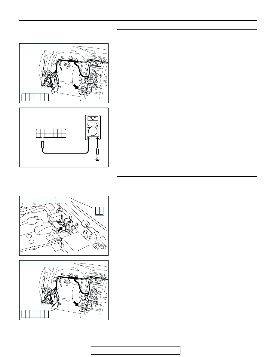
STEP 2. Check the immobilizer-ECU power supply circuit 
by backprobing.
(1) Do not disconnect immobilizer-ECU connector D-121.
(2) Turn the ignition switch to the "ON" position.

(3) Measure the voltage between terminal 7 and ground by 

backprobing.

Q: Is battery voltage (approximately 12 volts) present?

YES : Go to Step 5.
NO :  Go to Step 3.

STEP 3. Check immobilizer-ECU connector D-121 and MFI 
relay connector B-22X for loose, corroded or damaged 
terminals, or terminals pushed back in the connector.
Q: Are immobilizer-ECU connector D-121 and MFI relay 

connector B-22X damaged?
YES : 
Repair or replace them. Refer to GROUP 00E, 

Harness Connector Inspection 

P.00E-2

. Confirm that 

scan tool MB991502 communicates normally.

NO :  Go to Step 4.

AC204170

CONNECTOR : D-121

CV

HARNESS SIDE

2

3

8 7

9

10

1
6

5

12

4

11

AC204738 EB

HARNESS SIDE: D-121

4

3

2
7 8 9 10 11

5

12

1

6

AC204745

CONNECTOR : B-22X

AB

1
3 4

2

AC204170

CONNECTOR : D-121

CV

HARNESS SIDE

2

3

8 7

9

10

1
6

5

12

4

11

IGNITION SWITCH

TSB Revision

CHASSIS ELECTRICAL

54A-16

STEP 4. Check the harness wires between immobilizer-
ECU connector D-121 and MFI relay connector B-22X.

NOTE: Also check intermediate connector E-111 and joint con-
nector D-116,check the wires. If intermediate connector E-111 
and joint connector D-116 are damaged, repair or replace 
them. Refer to GROUP 00E, Harness Connector Inspection 

P.00E-2

.

Q: Are the harness wires between immobilizer-ECU 

connector D-121 and MFI relay connector B-22X 
damaged?
YES : 
Replace them. Confirm that scan tool MB991502 

communicates normally.

NO :  There is no action to be taken.

AC204745

CONNECTOR : B-22X

AB

1
3 4

2

AC204170

CONNECTOR : D-121

CV

HARNESS SIDE

2

3

8 7

9

10

1
6

5

12

4

11

AC204171

CONNECTOR : D-116

AD

9 10

8

6 7

31 32

30

29

18 19 20 21

5

4

2

1

3

27

26

24

23

25

12 13 14 15 16 17

28

11
22
33

AC204176

CONNECTOR : E-111

BF

15

4

14

37

36

26 27

12

11

35

34

23 24

3

13

25

9

2

8

32

20 21

6

5

17

29

30

18

1

7

19

31

10

22

33

16

28

38

IGNITION SWITCH

TSB Revision

CHASSIS ELECTRICAL

54A-17

STEP 5. Check the immobilizer-ECU ground circuit by 
backprobing.
(1) Do not disconnect immobilizer-ECU connector D-121. 

(2) Measure the resistance between terminal 3 and ground by 

backprobing.

Q: Is the resistance less than 2 ohms?

YES : Go to Step 7.
NO :  Go to Step 8.

STEP 6. Check immobilizer-ECU connector D-121 for 
loose, corroded or damaged terminals, or terminals 
pushed back in the connector.
Q: Is immobilizer-ECU connector D-121 in good condition?

YES : Go to Step 7.
NO :  Repair or replace it. Refer to GROUP 00E, Harness 

Connector Inspection 

P.00E-2

. Confirm that scan tool 

MB991502 communicates normally.

AC204170

CONNECTOR : D-121

CV

HARNESS SIDE

2

3

8 7

9

10

1
6

5

12

4

11

AC204738 EH

HARNESS SIDE: D-121

4

3

2
7 8 9 10 11

5

12

1

6

AC204170

CONNECTOR : D-121

CV

HARNESS SIDE

2

3

8 7

9

10

1
6

5

12

4

11

IGNITION SWITCH

TSB Revision

CHASSIS ELECTRICAL

54A-18

STEP 7. Check the harness wire between immobilizer-ECU 
connector D-121 and ground.
NOTE: Also check intermediate connector D-30, check the 
wires. If intermediate connector D-30 is damaged, repair or 
replace it. Refer to GROUP 00E, Harness Connector Inspec-
tion 

P.00E-2

.

Q: Is the harness wire between immobilizer-ECU connector 

D-121 and ground damaged?
YES : 
Repair it. Confirm that scan tool MB991502 

communicates normally.

NO :  There is no action to be taken.

STEP 8. Check the harness wires between immobilizer-
ECU connector D-121 and PCM connector D-110.
Q: Are the harness wires between immobilizer-ECU 

connector D-121 and PCM connector D-110 damaged?
YES : 
Repair them. Confirm that scan tool MB991502 

communicates normally.

NO :  Go to Step 9.

STEP 9. Replace the immobilizer-ECU or PCM.
Replace the immobilizer-ECU or PCM.
Q: Did the communication with the scan tool become 

possible after replacing the immobilizer-ECU or the 
power train control module?
YES : 
Register the password (secret code) and encrypted 

code 

P.54A-22

. Confirm that scan tool MB991502 

communicates normally

NO :  Go to Step 10.

AC204188

CONNECTORS : D-30, D-121

D-30

BP

D-30

D-121

D-121

9 10

8

6 7

31 32

30

29

18 19 20 21

5

4

2

1

3

27

26

24

23

25

12 13 14 15 16 17

28

11
22
33

HARNESS SIDE

2

3

8 7

9

10

1
6

5

12

4

11

AC204170

CONNECTOR : D-121

CV

HARNESS SIDE

2

3

8 7

9

10

1
6

5

12

4

11


Content   ..  459  460  461  462   ..