Mitsubishi Montero (2002-2004). Manual - part 455
 

  Index      Mitsubishi     Mitsubishi Montero - service repair manual 2002-2004 year


Search            


Content   ..  453  454  455  456   ..


Mitsubishi Montero (2002-2004). Manual - part 455


CRANKSHAFT AND CYLINDER BLOCK

TSB Revision

ENGINE OVERHAUL

11B-53

CYLINDER BLOCK
1. Visually check for scratches, rust, and corrosion. Use also a 

flaw detecting agent for the check. If defects are evident, 
correct, or replace.

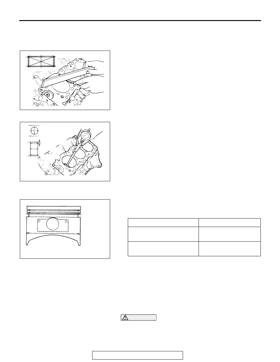
2. Using a straightedge and feeler gauge, check the block top 

surface for warpage. Make sure that the surface is free from 
gasket chips and other foreign matter.

Standard value: 0.05 mm (0.002 inch)
Limit: 0.1 mm (0.003 inch)

3. If the distortion is excessive, correct within the allowable 

limit or replace.

Grinding limit: *0.2 mm (0.008 inch)
 *Includes/combined with cylinder head grinding.
Cylinder block height (when new): 
227.9 

 228.1 mm (8.972  8.980 inches)

4. Check the cylinder walls for scratches and seizure. If defects 

are evident, correct (bored to an oversize) or replace.

5. Using a cylinder gauge, measure the cylinder bore and 

cylindricality. If worn badly, correct by boring the cylinders to 
an oversize and replace pistons and piston rings. Measure 
at the points shown in the illustration.

Standard value:
Cylinder Inside Diameter: 95.0 mm (3.740 inches) 
Cylindricality: 0.01 mm (0.0003 inch)

.

BORING CYLINDER 
1. Oversize pistons to be used should be determined on the 

basis of the largest bore cylinder.

     Piston size identification

NOTE: Size mark is stamped on the piston top.

2. Measure the outside diameter of the piston to be used. 

Measure it in the thrust direction as shown.

3. Based on the measured piston Outside Diameter (OD), 

calculate the boring finish dimension.

Boring finish dimension = Piston OD + (clearance 
between piston OD and cylinder) 

 0.02 mm (0.0008 

inch) (honing margin)

CAUTION

To prevent distortion that may result from temperature rise 
during honing, bore cylinders in the order of number 2, 
number 4, number 6, number 1, number 3 and number 5.
4. Bore all cylinders to the calculated boring finish dimension.

AKX00738

AKX00739AB

12 mm (0.47 in)

BOTTOM

CENTER

SIZE

IDENTIFICATION MARK

0.25 mm (0.010 in) Oversize 
diameter

0.25

0.50 mm (0.020 in) Oversize 
diameter

0.50

AKX00740

PISTON OUTSIDE
DIAMETER

THRUST 
DIRECTION

AB

BRACKET

TSB Revision

ENGINE OVERHAUL

11B-54

5. Hone to the final finish dimension (piston OD + clearance 

between piston OD and cylinder).

Standard value: 
Cylinder Inside Diameter: 95.0 mm (3.740 inches) 
Cylindricality: 0.01 mm (0.0003 inch)

6. Check the clearance between the piston and cylinder.

Clearance between piston and cylinder: 
0.02 

 0.04 mm (0.0008  0.0015 inch)

NOTE: When boring cylinders, finish all six cylinders to the 
same oversize. Do not bore only one cylinder to an oversize.

BRACKET

REMOVAL AND INSTALLATION

M1113009000084

AKX01390

75 ± 10 N·m
55 ± 7 ft-lb

41 ± 8 N·m
30 ± 6 ft-lb

75 ± 10 N·m
55 ± 7 ft-lb

2

1

AB

REMOVAL STEPS

1.

ENGINE SUPPORT BRACKET, 
RIGHT

2.

ENGINE SUPPORT BRACKET, 
LEFT

SPECIFICATIONS

TSB Revision

ENGINE OVERHAUL

11B-55

SPECIFICATIONS

FASTENER TIGHTENING SPECIFICATIONS

M1113023400406

ITEMS

SPECIFICATIONS

Generator and drive belt
Accessory mount bolt M10 pitch 1.25

44 

± 10 N⋅m (33 ± 7 ft-lb)

Accessory mount bolt M10 pitch 1.5

41 

± 8 N⋅m (30 ± 6 ft-lb)

Accessory mount bolt M12

74 

± 9 N⋅m (54 ± 7 ft-lb)

Accessory mount stay bolt

24 

± 4 N⋅m (17 ± 3 ft-lb)

Auto tensioner bolt M10

44 

± 10 N⋅m (33 ± 7 ft-lb)

Auto tensioner bolt M8

24 

± 4 N⋅m (17 ± 3 ft-lb)

Cooling fan bolt

11 

± 1 N⋅m (97 ±9 in-lb)

Cooling fan clutch bracket bolt

41 

± 8 N⋅m (30 ± 6 ft-lb)

Crankshaft bolt

185 

± 5 N⋅m (137 ± 3 ft-lb)

Fan clutch nut

11 

± 1 N⋅m (97 ± 9 in-lb)

Generator bolt M10

44 

± 10 N⋅m (33 ± 7 ft-lb)

Generator bolt M8 

22 

± 4 N⋅m (16 ± 3 ft-lb)

Idler pulley bolt

44 

± 10 N⋅m (33 ± 7 ft-lb)

Power steering pump bracket bolt

44 

± 10 N⋅m (33 ± 7 ft-lb)

Timing indicator bolt

11 

± 1 N⋅m (97 ± 9 in-lb)

Intake manifold plenum and throttle body
Intake manifold plenum bolt M8

18 

± 2 N⋅m (13 ± 2 ft-lb)

Intake manifold plenum bolt and nut M6

± 1 N⋅m (80 ± 9 in-lb)

Exhaust gas recirculation pipe bolt

18 

± 2 N⋅m (13 ± 2 ft-lb)

Exhaust gas recirculation pipe flare nut

59 

± 10 N⋅m (43 ± 7 ft-lb)

Exhaust gas recirculation valve bolt

24 

± 3 N⋅m (18 ± 2 ft-lb)

Fuel return pipe bolt

± 1 N⋅m (80 ± 9 in-lb)

Intake manifold plenum stay bolt M10

36 

± 6 N⋅m (27 ± 4 ft-lb)

Intake manifold plenum stay bolt M8

18 

± 2 N⋅m (13 ± 2 ft-lb)

Intake manifold plenum valve assembly bolt

18 

± 2 N⋅m (13 ± 2 ft-lb)

Manifold differential pressure sensor bolt

± 1 N⋅m (44 ± 9 in-lb)

Throttle body bolt

13 

± 2 N⋅m (113 ± 17 in-lb)

Solenoid valve bolt

± 1 N⋅m (80 ± 9 in-lb)

Water outlet fitting bracket bolt

14 

± 1 N⋅m (124 ± 9 in-lb)

Ignition system
Camshaft position sensing cylinder bolt

22 

± 4 N⋅m (16 ± 3 ft-lb)

Camshaft position sensor bolt

11 

± 1 N⋅m (97 ± 9 in-lb)

Camshaft position sensor support bolt

14 

± 1 N⋅m (124 ± 9 in-lb)

Ignition coil bolt

10 

± 2 N⋅m (89 ± 17 in-lb)

Spark plugs

25 

± 5 N⋅m (18 ± 4 ft-lb)

Spark plug cable support M8

13 

± 2 N⋅m (115 ± 18 in-lb)

Spark plug cable support M6

10 

± 2 N⋅m (89 ± 17 in-lb)

SPECIFICATIONS

TSB Revision

ENGINE OVERHAUL

11B-56

Timing belt
Auto tensioner bolt

24 

± 3 N⋅m (17 ± 2 ft-lb)

Camshaft sprocket bolt

88 

± 10 N⋅m (65 ± 8 ft-lb)

Crankshaft position sensor bolt washer assembly

8.5 

± 0.5 N⋅m (76 ± 4 in-lb)

Crankshaft position sensor flange bolt

11 

± 1 N⋅m (97 ± 9 in-lb)

Idler pulley bolt

44 

± 10 N⋅m (33 ± 7 ft-lb)

Tensioner arm bolt

44 

± 10 N⋅m (33 ± 7 ft-lb)

Tensioner pulley bolt

48 

± 6 N⋅m (35 ± 4 ft-lb)

Timing belt front cover bolt M6

11 

± 1 N⋅m (97 ± 9 in-lb)

Timing belt front cover bolt M8

14 

± 1 N⋅m (124 ± 9 in-lb)

Timing belt rear cover bolt

14 

± 1 N⋅m (124 ± 9 in-lb)

Intake manifold and fuel parts
Engine coolant temperature gauge unit

11 

± 1 N⋅m (97 ± 9 in-lb)

Engine coolant temperature sensor

29 

± 10 N⋅m (22 ± 7 ft-lb)

Fitting bolt

12 

± 1 N⋅m (106 ± 9 in-lb)

Fuel pipe bolt

± 1 N⋅m (80 ± 9 in-lb)

Fuel pressure regulator bolt

± 1 N⋅m (80 ± 9 in-lb)

Injector and fuel rail bolt

12 

± 1 N⋅m (106 ± 9 in-lb)

Intake manifold nut

22 

± 1 N⋅m (16 ± 1 ft-lb)

Thermostat case bolt

± 1 N⋅m (80 ± 9 in-lb)

Water inlet fitting bolt

12 

± 1 N⋅m (106 ± 9 in-lb)

Water outlet fitting bolt

12 

± 1 N⋅m (106 ± 9 in-lb)

Water outlet pipe bolt

14 

± 1 N⋅m (124 ± 9 in-lb)

Water passage bolt

19 

± 1 N⋅m (14 ± 1 ft-lb)

Water pipe bolt

14 

± 1 N⋅m (124 ± 9 in-lb)

Exhaust manifold
Oil dipstick guide bolt

14 

± 1 N⋅m (124 ± 9 in-lb)

Engine hanger bolt

36 

± 6 N⋅m (27 ± 4 in-lb)

Exhaust manifold nut

44 

± 5 N⋅m (33 ± 4 ft-lb)

Exhaust manifold cover bolt

14 

± 1 N⋅m (124 ± 9 in-lb)

Water pump bolt

24 

± 3 N⋅m (17 ± 2 ft-lb)

Rocker arm and camshaft
Rocker cover bolt

3.4 

± 0.5 N⋅m (26 ± 4 in-lb)

Rocker shaft bolt

31 

± 3 N⋅m (23 ± 2 ft-lb)

Thrust case bolt

13 

± 2 N⋅m (113 ± 17 in-lb)

Cylinder head and valve
Cylinder head bolt

108 

± 5 N⋅ m(80 ± 4 ft-lb) → back 

off 

→108 ± 5 N⋅ m(80 ± 4 ft-lb) 

Oil pan and oil pump
Baffle plate bolt

11 

± 1 N⋅m (97 ± 9 in-lb)

ITEMS

SPECIFICATIONS


Content   ..  453  454  455  456   ..