Mitsubishi Montero (2002-2004). Manual - part 376
INPUT SIGNAL PROCEDURES
TSB Revision
SWS INPUT SIGNAL PROCEDURES
54Bc-51
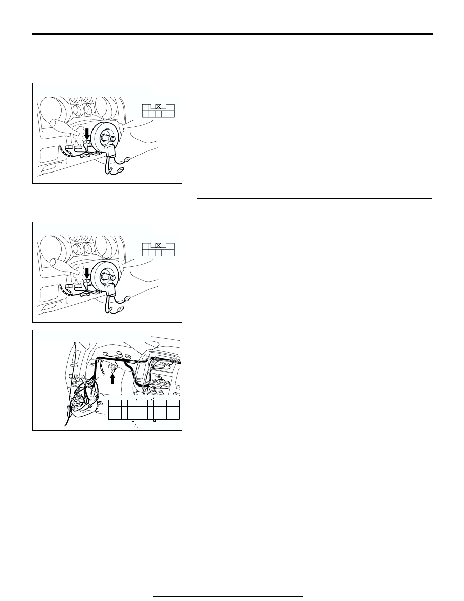
STEP 3. Check key reminder switch connector D-202 for
loose, corroded or damaged terminals, or terminals
pushed back in the connector.
Q: Is key reminder switch connector D-202 in good
condition?
YES : Go to Step 4.
NO : Repair or replace the damaged component(s). Refer
to GROUP 00E, Harness Connector Inspection
. If the functions, which are described in
"CIRCUIT OPERATION", work normally, the input
signal from the key reminder switch should be normal.
STEP 4. Check the wiring harness between key reminder
switch connector D-202 (terminal 4) and ground.
NOTE: Also check joint connector D-30 for loose, corroded, or
damaged terminals, or terminals pushed back in the connector.
If joint connector D-30 is damaged, repair or replace the dam-
aged component(s) as described in GROUP 00E, Harness
Connector Inspection
.
Q: Is the wiring harness between key reminder switch
connector D-202 (terminal 4) and ground in good
condition?
YES : No action is necessary and testing is complete.
NO : The wiring harness may be damaged or the
connector(s) may have loose, corroded or damaged
terminals, or terminals pushed back in the connector.
Repair the wiring harness as necessary. If the
functions, which are described in "CIRCUIT
OPERATION", work normally, the input signal from
the key reminder switch should be normal.
AC204172
CONNECTOR : D-202
AB
HARNESS SIDE
4
5
3
1
6
7
2
D-203
AC204172
CONNECTOR : D-202
AB
HARNESS SIDE
4
5
3
1
6
7
2
D-203
AC204170
CONNECTOR : D-30
AJ
9 10
8
6 7
31 32
30
29
18 19 20 21
5
4
2
1
3
27
26
24
23
25
12 13 14 15 16 17
28
11
22
33