Mitsubishi Montero (2002-2004). Manual - part 317
 

  Index      Mitsubishi     Mitsubishi Montero - service repair manual 2002-2004 year


Search            


Content   ..  315  316  317  318   ..


Mitsubishi Montero (2002-2004). Manual - part 317


SYMPTOM PROCEDURES

TSB Revision

SWS SYMPTOM PROCEDURES

54Bb-315

STEP 2. Check the input signal by using "FUNCTION 
DIAG." menu of the SWS monitor.
Check the input signals from the following switches:

• Ignition switch: ON

• Lighting switch: HEAD

• Dimmer switch: ON

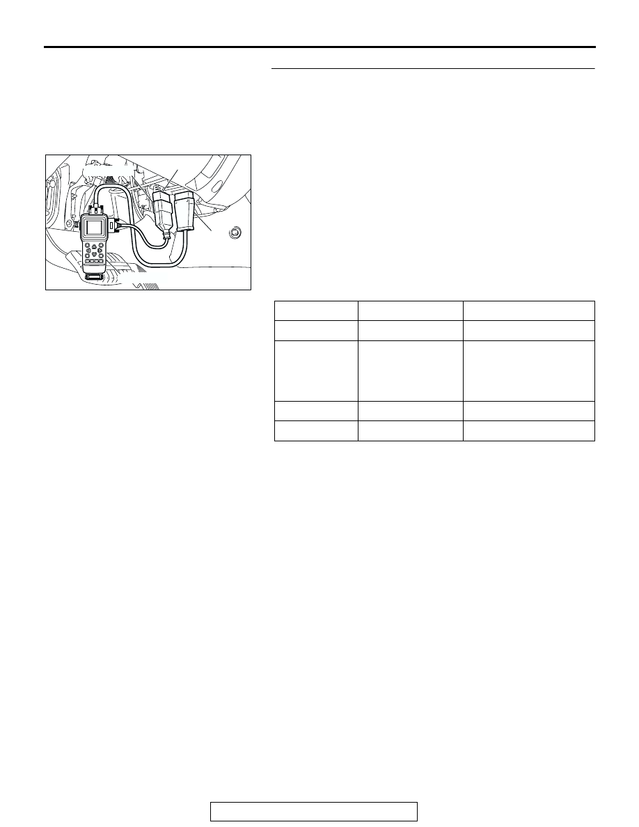
Operate scan tool MB991502 according to the procedure below 
to display "HEADLIGHT HI."

1. Select "SYSTEM SELECT."
2. Select "SWS."
3. Select "SWS MONITOR."
4. Select "FUNCTION DIAG."
5. Select "LIGHTING."
6. Select "HEADLIGHT HI."

Check that normal conditions are displayed on the items 
described in the table below.

Q: Are normal conditions displayed on the "HEADLIGHT 

SW", "DIMMER SW", "H/L AUTO-CUT" and "FRONT 
ECU ACK"?
YES : 
Go to Step 3.
NO : 

• Normal condition is not displayed on the 

"HEADLIGHT SW": Refer to Inspection Procedure 
O-6 "ETACS-ECU does not receive any signal 
from the headlight switch 

P.54Bc-31

."

• Normal condition is not displayed on the 

"DIMMER SW": Refer to Inspection Procedure O-
6 "ETACS-ECU does not receive any signal from 
the dimmer switch 

P.54Bc-31

."

• Normal condition is not displayed on the "H/L 

AUTO-CUT": Refer to Inspection Procedure J-9 
"Headlight automatic shutdown function does not 
work normally 

P.54Bb-373

."

• Normal condition is not displayed on the "FRONT 

ECU ACK": Replace the front-ECU. Verify that the 
headlights (high-beam) illuminate normally.

ITEM NO.

ITEM NAME

NORMAL CONDITION

ITEM 00

HEADLIGHT SW

ON

ITEM 02

DIMMER SW

OFF (should turn "ON" 
momentarily when the 
dimmer switch is 
operated)

ITEM 35

H/L AUTO-CUT

OFF

ITEM 70

FRONT ECU ACK HI-BEAM ACK

AC204222AB

16-pin

13-pin

MB991502

MB991862

SYMPTOM PROCEDURES

TSB Revision

SWS SYMPTOM PROCEDURES

54Bb-316

STEP 3. Check the battery power supply circuit to the 
front-ECU. Test at front-ECU connector A-07X.
(1) Disconnect front-ECU connector A-07X and measure the 

voltage available at the relay box side of the connector.

(2) Measure the voltage between terminal 3 and ground.

• The voltage should be approximately 12 volts (battery 

positive voltage).

Q: Is the measured voltage approximately 12 volts (battery 

positive voltage)?
YES : 
Replace the front-ECU. Verify that the headlights 

(low-beam) illuminate normally.

NO :  Go to Step 4.

STEP 4. Check the front-ECU connector A-07X for loose, 
corroded or damaged terminals, or terminals pushed back 
in the connector.
Q: Is the front-ECU connector A-07X in good condition?

YES : Go to Step 5.
NO :  Repair or replace the damaged component(s). Refer 

to GROUP 00E, Harness Connector Inspection 

P.00E-2

. Verify that the headlights (low-beam) 

illuminate normally.

AC204183

CONNECTOR : A-07X

AB

2 1

3

4

6

7

8

9

5

11 10

RELAY BOX SIDE

AC204761

1

2

3

4

5

6

7

8

9

10

11

CONNECTOR A-07X
(RELAY BOX SIDE)

AB

AC204183

CONNECTOR : A-07X

AB

2 1

3

4

6

7

8

9

5

11 10

RELAY BOX SIDE

SYMPTOM PROCEDURES

TSB Revision

SWS SYMPTOM PROCEDURES

54Bb-317

STEP 5. Check the wiring harness between front-ECU 
connector A-07X (terminal 3) and the battery.
Q: Is the wiring harness between front-ECU connector A-

07X (terminal 3) and the battery in good condition?
YES : 
No action is necessary and testing is complete.
NO :  The wiring harness may be damaged or the 

connector(s) may have loose, corroded or damaged 
terminals, or terminals pushed back in the connector. 
Repair the wiring harness as necessary. Verify that 
the headlights (low-beam) illuminate normally. 

INSPECTION PROCEDURE J-4: Headlight and Taillight: Headlights do not illuminate when the 
passing switch is operated.

NOTE: This troubleshooting procedure requires the 
use of scan tool MB991502 and SWS monitor kit 
MB991862. For details on how to use the SWS mon-
itor, refer to "How to use SWS monitor 

P.54Ba-8

."

.

TECHNICAL DESCRIPTION (COMMENT) 
If both of the headlights (low-beam and high-beam) 
do not illuminate, the input circuit from the passing 
switch or the front-ECU may be defective.

.

TROUBLESHOOTING HINTS

• The column switch may be defective

• The front-ECU may be defective

• The wiring harness or connectors may have 

loose, corroded, or damaged terminals, or termi-
nals pushed back in the connector

DIAGNOSIS

Required Special Tools:

• MB991223: Harness Set

• MB991502: Scan Tool (MUT-II)

• MB991862: SWS monitor kit

STEP 1. Verify the headlight operation.
Q: Do the headlights (low-beam and high-beam) illuminate 

normally?
YES : 
Go to Step 2.
Headlights (low-beam) do not illuminate normally : 

Refer to Inspection Procedure J-2 "Headlights (low-
beam) do not illuminate normally 

P.54Bb-308

."

Headlights (high-beam) do not illuminate normally : 

Refer to Inspection Procedure J-3 "Headlights (high-
beam) do not illuminate normally 

P.54Bb-313

."

AC204183

CONNECTOR : A-07X

AB

2 1

3

4

6

7

8

9

5

11 10

RELAY BOX SIDE

SYMPTOM PROCEDURES

TSB Revision

SWS SYMPTOM PROCEDURES

54Bb-318

STEP 2. Check the input signal by using "DATA LIST" 
menu of the SWS monitor.
Turn the passing switch to the "ON" position before checking 
input signals from the passing switch.

CAUTION

To prevent damage to scan tool MB991502, always turn the 
ignition switch to the "LOCK" (OFF) position before con-
necting or disconnecting scan tool MB991502.
(1) Connect scan tool MB991502 to the data link connector 

(16-pin).

(2) Connect SWS monitor kit MB991862 to the data link 

connector (13-pin).

(3) Operate scan tool MB991502 according to the procedure 

below to display "COLUMN ECU."

1. Select "SYSTEM SELECT."
2. Select "SWS."
3. Select "SWS MONITOR."
4. Select "DATA LIST."
5. Select "COLUMN ECU."

(4) Check that normal conditions are displayed on the items 

described in the table below.

Q: Is normal condition displayed on the "PASSING SW"?

YES : Replace the front-ECU. When the passing switch is 

operated, the headlights (low-beam and high-beam) 
should illuminate normally.

NO :  Refer to Inspection Procedure O-6 "ETACS-ECU 

does not receive any signal from the passing switch 

P.54Bc-31

."

INSPECTION PROCEDURE J-5: Headlight and Taillight: Headlights do not illuminate when the lighting 
switch is at "TAIL," and "PASSING" position, but illuminate at low-beam when the switch is at "HEAD" 
position. At this position, the headlights cannot be changed into high beam by operating the dimmer 
switch.

NOTE: This troubleshooting procedure requires the 
use of scan tool MB991502 and SWS monitor kit 
MB991862. For details on how to use the SWS mon-
itor, refer to "How to use SWS monitor" 

P.54Ba-8

.

.

TECHNICAL DESCRIPTION (COMMENT)
If the headlights illuminate at low-beam regardless of 
the lighting switch positions, the headlight operation 
is in fail-safe mode.

.

TROUBLESHOOTING HINTS

• The column switch may be defective

• The front-ECU may be defective

• The ETACS-ECU may be defective

• The wiring harness or connectors may have 

loose, corroded, or damaged terminals, or termi-
nals pushed back in the connector

ITEM NO.

ITEM NAME

NORMAL CONDITION

ITEM 03

PASSING SW

ON

AC204222AB

16-pin

13-pin

MB991502

MB991862


Content   ..  315  316  317  318   ..