Mitsubishi Montero (2002-2004). Manual - part 243
 

  Index      Mitsubishi     Mitsubishi Montero - service repair manual 2002-2004 year


Search            


Content   ..  241  242  243  244   ..


Mitsubishi Montero (2002-2004). Manual - part 243


SYMPTOM PROCEDURES

TSB Revision

SWS SYMPTOM PROCEDURES

54Bb-19

STEP 2. Check column switch connector D-203 for loose, 
corroded or damaged terminals, or terminals pushed back 
in the connector.
Q: Is column switch connector D-203 in good condition?

YES : Go to Step 3.
NO :  Repair or replace the damaged component(s). The 

system should communicate with the column switch 
(column-ECU) normally.

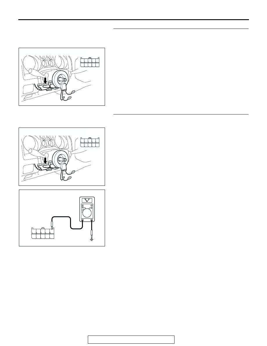
STEP 3. Check the battery power supply circuit to the 
column switch. Test at column switch connector D-203.
(1) Disconnect column switch connector D-203 and measure 

the voltage available at the wiring harness side of the 
connector.

(2) Measure the voltage between terminal 1 and ground by 

backprobing.

• The voltage should be approximately 12 volts (battery 

positive voltage).

Q: Is the measured voltage approximately 12 volts (battery 

positive voltage)?
YES : 
Go to Step 6.
NO :  Go to Step 4.

AC204172

CONNECTOR : D-203

AC

HARNESS SIDE

1

2

3

7

8

6

5

10

4

9

D-203

AC204172

CONNECTOR : D-203

AC

HARNESS SIDE

1

2

3

7

8

6

5

10

4

9

D-203

5 4 3 2 1

10 9 8 7 6

AC203693

CONNECTOR D-203
(HARNESS SIDE)

AC

SYMPTOM PROCEDURES

TSB Revision

SWS SYMPTOM PROCEDURES

54Bb-20

STEP 4. Check column switch connector D-203 for loose, 
corroded or damaged terminals, or terminals pushed back 
in the connector.
Q: Is column switch connector D-203 in good condition?

YES : Go to Step 5.
NO :  Repair or replace the damaged component(s). Refer 

to GROUP 00E, Harness Connector Inspection 

P.00E-2

. The system should communicate with the 

column switch (column-ECU) normally.

STEP 5. Check the wiring harness between column switch 
connector D-203 (terminal 1) and the battery.

NOTE: Also check intermediate connector D-28 for loose, cor-
roded, or damaged terminals, or terminals pushed back in the 
connector. If intermediate connector D-28 is damaged, repair or 
replace the damaged component(s) as described in GROUP 
00E, Harness Connector Inspection 

P.00E-2

.

Q: Is the wiring harness between column switch connector 

D-203 (terminal 1) and the battery in good condition?
YES : 
No action is necessary and testing is complete.
NO :  The wiring harness may be damaged or the 

connector(s) may have loose, corroded or damaged 
terminals, or terminals pushed back in the connector. 
Repair the wiring harness as necessary. The system 
should communicate with the column switch (column-
ECU) normally.

AC204172

CONNECTOR : D-203

AC

HARNESS SIDE

1

2

3

7

8

6

5

10

4

9

D-203

AC204172

CONNECTOR : D-203

AC

HARNESS SIDE

1

2

3

7

8

6

5

10

4

9

D-203

AC204170

CONNECTOR : D-28

AI

2 3

27

32

28

33

16

15

4 5

19

18

29

17

34

7 8

35

22

21

9 10

30

36

31

37

25

24

23

6

20

1

14

26

11

13

12

38

SYMPTOM PROCEDURES

TSB Revision

SWS SYMPTOM PROCEDURES

54Bb-21

STEP 6. Check the ground circuit to the column switch. 
Test at column switch connector D-203.
(1) Disconnect column switch connector D-203 and measure 

the resistance available at the wiring harness side of the 
connector.

(2) Measure the resistance value between terminal 4 and 

ground.

• The resistance should equal 2 ohms or less.

Q: Is the measured resistance 2 ohms or less?

YES : Go to Step 9.
NO :  Go to Step 7.

STEP 7. Check column switch connector D-203 for loose, 
corroded or damaged terminals, or terminals pushed back 
in the connector.
Q: Is column switch connector D-203 in good condition?

YES : Go to Step 8.
NO :  Repair or replace the damaged component(s). Refer 

to GROUP 00E, Harness Connector Inspection 

P.00E-2

. The system should communicate with the 

column switch (column-ECU) normally.

STEP 8. Check the wiring harness between column switch 
connector D-203 (terminal 4) and the ground.
Q: Is the wiring harness between column switch connector 

D-203 (terminal 4) and the ground in good condition?
YES : 
No action is necessary and testing is complete.
NO :  The wiring harness may be damaged or the 

connector(s) may have loose, corroded or damaged 
terminals, or terminals pushed back in the connector. 
Repair the wiring harness as necessary. The system 
should communicate with the column switch (column-
ECU) normally.

AC204172

CONNECTOR : D-203

AC

HARNESS SIDE

1

2

3

7

8

6

5

10

4

9

D-203

ACX00772

5 4 3 2 1

10 9 8 7 6

CONNECTOR D-203
(HARNESS SIDE)

AB

AC204172

CONNECTOR : D-203

AC

HARNESS SIDE

1

2

3

7

8

6

5

10

4

9

D-203

AC204172

CONNECTOR : D-203

AC

HARNESS SIDE

1

2

3

7

8

6

5

10

4

9

D-203

SYMPTOM PROCEDURES

TSB Revision

SWS SYMPTOM PROCEDURES

54Bb-22

STEP 9. Check column switch connector D-203 and 
ETACS-ECU connector D-224 for loose, corroded or 
damaged terminals, or terminals pushed back in the 
connector.
Q: Are column switch connector D-203 and ETACS-ECU 

connector D-224 in good condition?
YES : 
Go to Step 10.
NO :  Repair or replace the damaged component(s). Refer 

to GROUP 00E, Harness Connector Inspection 

P.00E-2

. The system should communicate with the 

column switch (column-ECU) normally.

STEP 10. Check the wiring harness between column 
switch connector D-203 (terminal 3) and ETACS-ECU 
connector D-224 (terminal 21).
Q: Is the wiring harness between column switch connector 

D-203 (terminal 3) and ETACS-ECU connector D-224 
(terminal 21) in good condition?
YES : 
Go to Step 11.
NO :  The wiring harness may be damaged or the 

connector(s) may have loose, corroded or damaged 
terminals, or terminals pushed back in the connector. 
Repair the wiring harness as necessary. The system 
should communicate with the column switch (column-
ECU) normally.

AC204172

CONNECTOR : D-203

AC

HARNESS SIDE

1

2

3

7

8

6

5

10

4

9

D-203

AC204174

CONNECTOR : D-224

AD

D-224(B)

D-224(B)

HARNESS SIDE

21

23

24

22

32

3433

31

26

27

28

3029

38

39

40

36

37

25

35

AC204172

CONNECTOR : D-203

AC

HARNESS SIDE

1

2

3

7

8

6

5

10

4

9

D-203

AC204174

CONNECTOR : D-224

AD

D-224(B)

D-224(B)

HARNESS SIDE

21

23

24

22

32

3433

31

26

27

28

3029

38

39

40

36

37

25

35


Content   ..  241  242  243  244   ..