Content .. 1137 1138 1139 1140 ..
Mitsubishi Montero (2002-2004). Manual - part 1139
M-ASTC DIAGNOSIS
TSB Revision
MITSUBISHI ACTIVE SKID AND TRACTION CONTROL SYSTEM
35C-173
CAUTION
Always use the test harness when measuring the voltage
or resistance value at the female connector. If you fail to do
so, connectors may be damaged.
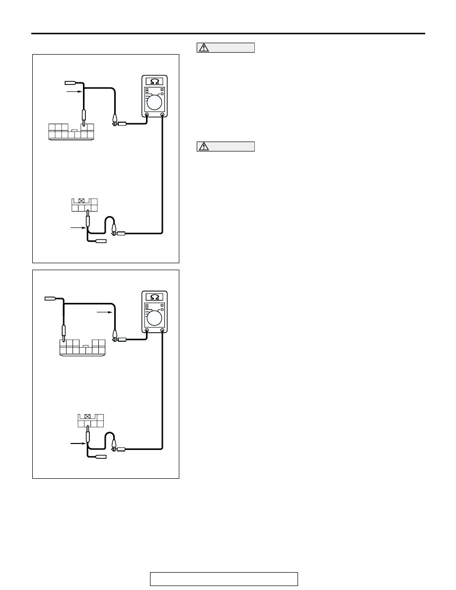
(4) Measure the resistance values between joint connector (9)
D-131 terminal 2 and steering wheel sensor connector D-
225 terminal 3, and between joint connector (9) D-131
terminal 5 and steering wheel sensor connector D-225
terminal 4.
• The resistance should measure 2 ohms or less.
CAUTION
If you repair the CAN bus line of the instrument panel wir-
ing harness assembly (the wiring harness connected to
the steering wheel sensor, the data link connector and the
resistor) and the transmission wiring harness assembly
(the wiring harness connected to the G and yaw rate sen-
sor connector and intermediate connector E-123), observe
the precautions regarding how to repair wiring harness. If
a new wire is added or a splice point is modified for the
CAN_L or CAN_H line, an error in the CAN communication
may be caused.
Q: Does the resistance measure 2 ohms or less?
YES : Diagnose the steering wheel sensor. Refer to
NO : Repair the wiring harness wires between joint
connector (9) and the steering wheel sensor
connector.
AC204582
HARNESS SIDE: D-225
AP
HARNESS SIDE: D-131
6
1
9 8
2
7
10
12 11
4
5
3
TEST
HARNESS
3 2
1
4
5
TEST
HARNESS
AC204582
HARNESS SIDE: D-225
AQ
HARNESS SIDE: D-131
6
1
9 8
2
7
10
12 11
4
5
3
TEST
HARNESS
3 2
1
4
5
TEST
HARNESS