Mitsubishi Montero (2002-2004). Manual - part 1060


  Index      Mitsubishi     Mitsubishi Montero - service repair manual 2002-2004 year


Search            


Content   ..  1058  1059  1060  1061   ..


Mitsubishi Montero (2002-2004). Manual - part 1060


ANTI-LOCK BRAKING SYSTEM (ABS) DIAGNOSIS

TSB Revision

ANTI-LOCK BRAKING SYSTEM (ABS)

35B-111

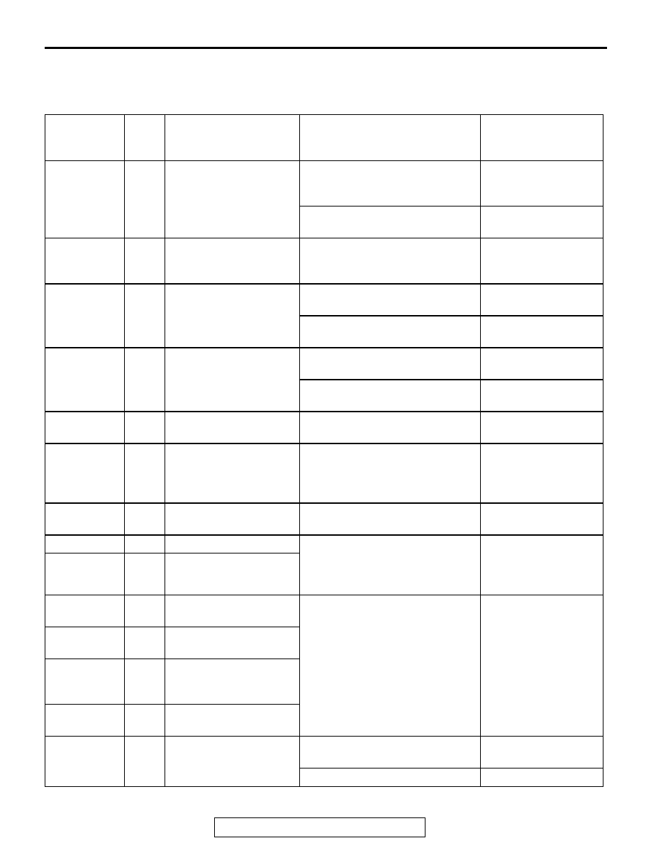
DATA LIST REFERENCE TABLE

M1352011500401

The following items can be read by the scan tool 
from the M-ASTC-ECU input data.

MUT-II SCAN 
TOOL 
DISPLAY*

ITEM 
NO.

CHECK ITEM

CHECKING REQUIREMENTS

NORMAL VALUE

ACCUM 
SW(PH)

77

Accumulator switch (PH) Accumulator fluid pressure 

reduces to less than approx. 16.1 
MPa

ON

Accumulator fluid pressure 
reaches approx. 18.3 MPa

OFF

ACCUM 
SW(PL)

76

Accumulator switch (PL) Accumulator fluid pressure 

reduces to approx. 10.8 MPa or 
less.

ON

M-ASTC OFF 
SW

37

Active skid control 
switch

Set the active skid control switch 
to the neutral position

OFF

Turn the active skid control switch 
to the OFF position

ON

M-ASTC ON 
SW

38

Active skid control 
switch

Set the active skid control switch 
to the neutral position

OFF

Turn the active skid control switch 
to the ON position

ON

BATT. 
VOLTAGE

31

M-ASTC-ECU power 
supply voltage

Ignition switch power supply 
voltage and valve monitor voltage

6.5 

− 22.3 V

ENGINE 
SPEED

17

Engine speed

Drive the vehicle

The scan tool and the 
tachometer readings 
are approximately the 
same

EN. TYPE/
DESTN

28

Engine model and 
destination

6G75 NAS

FR SNSR

11

Front right ABS sensor

Drive the vehicle

Vehicle speeds 
displayed on the 
speedometer and 
scan tool are identical.

FL SNSR

12

Front left ABS sensor

G SENS 
VOLT 1

22

Output 1 from G sensor Drive the vehicle

-14.7 

− 14.7 m/s

2

G SENS 
VOLT 2

23

Output 2 from G sensor

G SENSOR 
VOLT

19

Output from G sensor 
(longitudinal 
acceleration)


S(LATERAL)

20

Output from G sensor 
(lateral acceleration)

IDLE POS. 
SW

75

Closed throttle position 
switch

Do not depress the accelerator 
pedal

ON

Depress the accelerator pedal

OFF

ANTI-LOCK BRAKING SYSTEM (ABS) DIAGNOSIS

TSB Revision

ANTI-LOCK BRAKING SYSTEM (ABS)

35B-112

TR SWITCH

26

Transmission range 
switch

Drive the vehicle

The shift lever position 
indicator and the scan 
tool readings are 
equal

M/C PRESS. 
SNSR

24

Master cylinder pressure 
sensor

When depressing gradually the 
brake pedal, the output value will 
change.

Approximately 0.5 - 
4.5 V

MOTOR RLY 79

Motor relay

Motor relay is operating

ON

Motor relay is not operating

OFF

RR SNSR

13

Rear right ABS sensor

Drive the vehicle

Vehicle speeds 
displayed on the 
speedometer and 
scan tool are identical.

RL SNSR

14

Rear left ABS sensor

SHIFT 
POSIT.

27

Shift position

Drive the vehicle

The shift lever position 
indicator and the scan 
tool readings are 
equal

ST ANGLE

32

Steering wheel angle

Steering wheel angle

deg (approximately 
the same as actual 
steering wheel angle)

STOPLIGHT 
SW

36

Stoplight switch

Depress the brake pedal.

ON

Release the brake pedal.

OFF

T/F MODE

30

Transfer position

Drive the vehicle.

the same as actual 
transfer position

VALVE RLY

78

Valve relay

Valve relay is operating

ON

Valve relay is not operating

OFF

MUT-II SCAN 
TOOL 
DISPLAY*

ITEM 
NO.

CHECK ITEM

CHECKING REQUIREMENTS

NORMAL VALUE

ANTI-LOCK BRAKING SYSTEM (ABS) DIAGNOSIS

TSB Revision

ANTI-LOCK BRAKING SYSTEM (ABS)

35B-113

ACTUATOR TEST REFERENCE

M1352011600378

CAUTION

When performing the item No. 09 [AIR BLEEDING 
(1)] consecutively, keep the interval of 20 sec-
onds or more between respective bleeding oper-
ations. 
The scan tool activates the following actuators for 
testing.

NOTE: If the M-ASTC-ECU is inoperative, actuator 
testing cannot be carried out.
NOTE: Actuator testing is only possible when the 
vehicle is stationary. If the vehicle speed during actu-
ator testing exceeds 10 km/h (6 mph), forced actua-
tion will be canceled.

ACTUATOR TEST SPECIFICATIONS

MUT-II SCAN 
TOOL DISPLAY

ITEM 
NO.

CHECK ITEM

PARTS TO BE 
ACTIVATED

ACTIVATION 
WHEN THE 
SYSTEM 
FAILS

FR ABS VALVE

01

Solenoid valve for front-right wheel HBB select solenoid 

valves and control 
solenoid valves for the 
respective channel

Disabled

FL ABS VALVE

02

Solenoid valve for front-left wheel

RR ABS VALVE

03

Solenoid valve for rear-right wheel

RL ABS VALVE

04

Solenoid valve for rear-left wheel

ABS AIR B.1

09

Air bleeding (1)

HBB select solenoid 
valves and control 
solenoid valve OUT (FR, 
FL)

Disabled

ABS AIR B.2

10

Air bleeding (2)

HBB control solenoid 
valve OUT (RR, RL)

Disabled

ANTI-LOCK BRAKING SYSTEM (ABS) DIAGNOSIS

TSB Revision

ANTI-LOCK BRAKING SYSTEM (ABS)

35B-114

ACX01113AC

ON

OFF

ON

OFF

ON

OFF

ON

OFF

ON

OFF

ON

OFF

ON

OFF

ON

OFF

1s

2s

ITEM No. 01 - 04 DRIVE PATTERN

CONTROL SOLENOID 
VALVE IN

CONTROL SOLENOID 
VALVE OUT

SELECT SOLENOID 
VALVE (FR)

SELECT SOLENOID 
VALVE (FL)

CORRESPONDING 
WHEEL BRAKE PRESSURE

INCREASE

DECREASE

HOLD

INCREASE

ITEM No. 09, 10 DRIVE PATTERN

CONTROL SOLENOID 
VALVE OUT (RH)*

CONTROL SOLENOID 
VALVE OUT (LH)*

<ITEM No. 10 ONLY>

SELECT SOLENOID 
VALVE (FR)

SELECT SOLENOID 
VALVE (FL)

NOTE
*: WHEN CARRYING OUT ITEM No. 09, THE FRONT WHEELS ARE DRIVEN, AND WHEN 
    CARRYING OUT ITEM No. 10 THE REAR WHEELS ARE DRIVEN.

0.8s 0.8s

2.5s

0.8s

2.5s

0.8s 0.8s


Content   ..  1058  1059  1060  1061   ..