Mitsubishi Montero (1998+). Manual - part 140


  Index      Mitsubishi     Mitsubishi Montero - service repair manual 1998 year


Search            


Content   ..  138  139  140  141   ..


Mitsubishi Montero (1998+). Manual - part 140


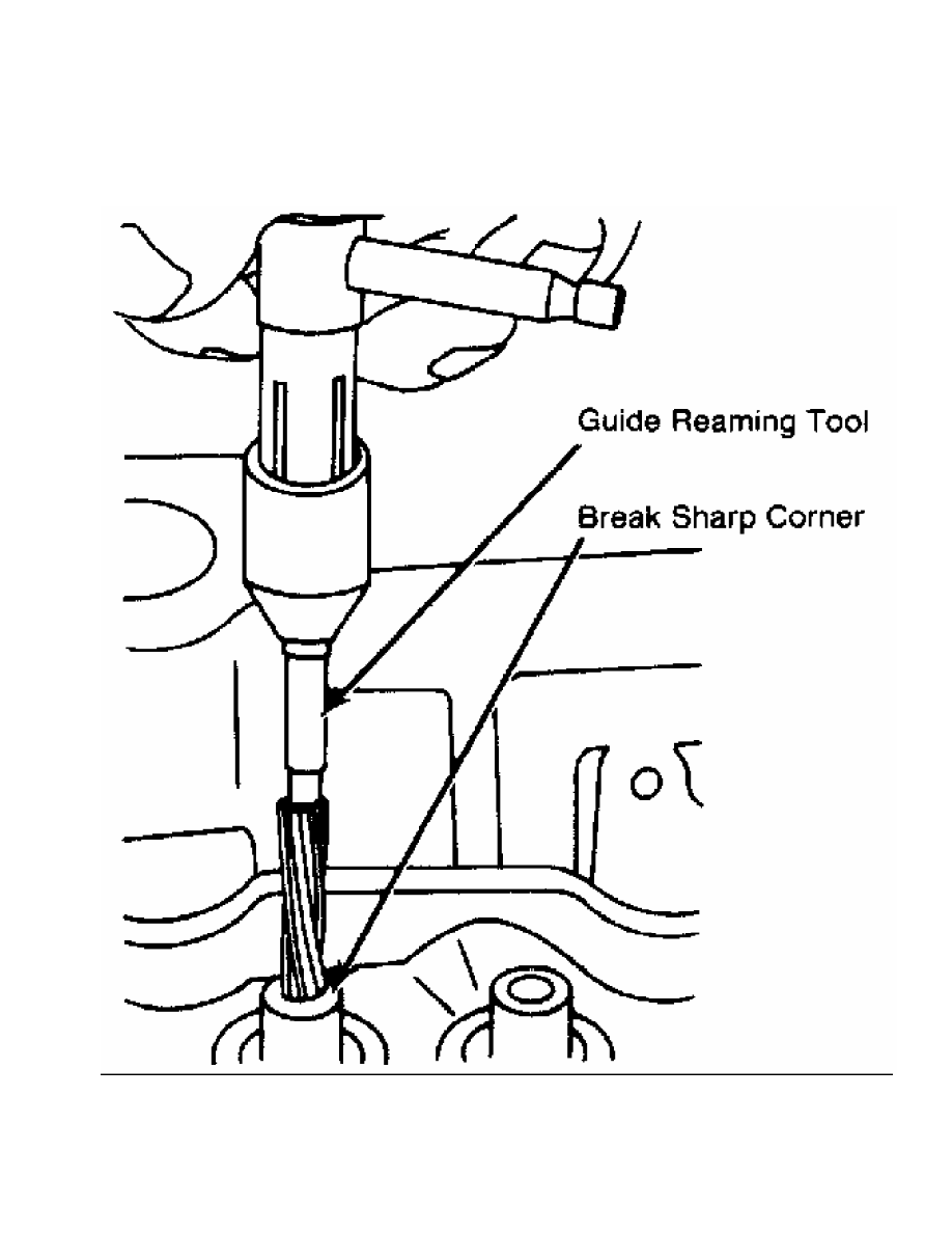
Fig. 7:  Reaming Valve Guides - Typical

This Graphic For General Information Only

         Replacing Valve Guide

         Replace valve guide if clearance exceeds specification. Valve

guides are either pressed, hammered or shrunk in place, depending upon

cylinder head design and type of metal used.

         Remove valve guide from cylinder head by pressing or tapping

on a stepped drift. See Fig. 8. Once valve guide is installed,

distance from cylinder head to top of valve guide must be checked.

This distance must be within specification.

         Aluminum heads are often heated before installing valve

guide. Guide is sometimes chilled in dry ice before installation.

Combination of a heated head and chilled guide insures a tight guide

fit upon assembly. The new guide must be reamed to specification.

Fig. 8:  Typical Valve Guide Remover & Installer

This Graphic For General Information Only

         VALVES & VALVE SEATS

         Valve Grinding

         Valve stem O.D. should be measured in several areas to

indicate amount of wear. Replace valve if not within specification.

Valve margin area should be measured to ensure that valve can be

grounded. See Fig. 9.

Fig. 9:  Measuring Valve Head Margin - Typical

This Graphic For General Information Only

         If valve margin is less than specification, this will burn

the valves. Valve must be replaced. Due to minimum margin dimensions

during manufacture, some new type valves cannot be reground.

         Resurface valve on proper angle specification using valve

grinding machine. Follow manufacturer’s instructions for valve

grinding machine. Specifications may indicate a different valve face

angle than seat angle.

         Measure valve margin after grinding. Replace valve if not

within specification. Valve stem tip can be refinished using valve

grinding machine.

         Valve Lapping

         During valve lapping of recent designed valves, be sure to

follow manufacturers recommendations. Surface hardening and materials

used with some valves do not permit lapping. Lapping process will

remove excessive amounts of the hardened surface.

         Valve lapping is done to ensure adequate sealing between

valve face and seat. Use either a hand drill or lapping stick with

suction cup attached.

         Moisten and attach suction cup to valve. Lubricate valve stem

and guide. Apply a thin coat of fine valve grinding compound between

valve and seat. Rotate lapping tool between the palms or with hand

drill.

         Lift valve upward off the seat and change position often.

This is done to prevent grooving of valve seat. Lap valve until a

smooth polished seat is obtained. Thoroughly clean grinding compound

from components. Valve to valve seat concentricity should be checked.

See VALVE SEAT CONCENTRICITY.

CAUTION: Valve guides must be in good condition and free of carbon

         deposits prior to valve seat grinding. Some engines contain

         an induction hardened valve seat. Excessive material removal

         will damage valve seats.

         Valve Seat Grinding

         Select coarse stone of correct size and angle for seat to be

ground. Ensure stone is true and has a smooth surface. Select correct

size pilot for valve guide dimension. Install pilot in valve guide.

Lightly lubricate pilot shaft. Install stone on pilot. Move stone off

and on the seat approximately 2 times per second during grinding

operation.

         Select a fine stone to finish grinding operation. Grinding

stones with 30 and 60 degree angles are used to center and narrow the

valve seat as required. See Fig. 10.

Fig. 10:  Adjusting Valve Seat Width - Typical

This Graphic For General Information Only

         Valve Seat Replacement

         Replacement of valve seat inserts is done by cutting out

the old insert and machining an oversize insert bore. Replacement

oversize insert is usually chilled and the cylinder head is sometimes

warmed. Valve seat is pressed into the head. This operation requires

specialized machine shop equipment.

         Valve Seat Concentricity

         Using dial gauge, install gauge pilot in valve guide.

Position gauge arm on the valve seat. Adjust dial indicator to zero.

Rotate arm 360 degrees and note reading. Runout should not exceed

specification.

         To check valve-to-valve seat concentricity, coat valve face

lightly with Prussian Blue dye. Install valve and rotate it on valve

seat. If pattern is even and entire seat is coated at valve contact

point, valve is concentric with the seat.

         REASSEMBLY

         Valve Stem Installed Height

         Valve stem installed height must be checked when new valves

are installed or when valves or valve seats have been ground. Install

valve in valve guide. Measure distance from tip of valve stem to

spring seat. See Fig. 11. Distance must be within specifications.

Fig. 11:  Measuring Valve Stem Installed Height - Typical

This Graphic For General Information Only

         Remove valve and grind valve stem tip if height exceeds

specification. Valve tips are surface hardened. DO NOT remove more


Content   ..  138  139  140  141   ..