Mitsubishi Montero (1998+). Manual - part 95


  Index      Mitsubishi     Mitsubishi Montero - service repair manual 1998 year


Search            


Content   ..  93  94  95  96   ..


Mitsubishi Montero (1998+). Manual - part 95


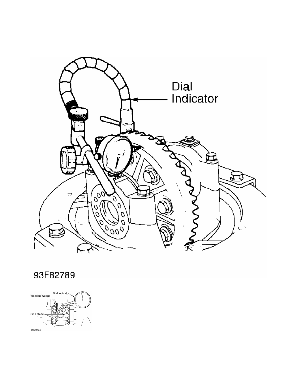
Fig. 7:  Measuring Ring Gear Runout

Courtesy of Mitsubishi Motor Sales of America.

Fig. 8:  Checking Pinion & Side Gear Backlash

Courtesy of Mitsubishi Motor Sales of America.

NOTE:    See DIFFERENTIAL ASSEMBLY (LIMITED SLIP) for carrier

         assembly and drive pinion installation.

         Carrier Assembly & Drive Pinion Removal

         1) Remove differential carrier from axle housing. Remove lock

plates. Mark location of side bearing nuts for reassembly. Remove side

bearing nuts. See Fig. 9. Mark location of bearing caps for

reassembly. Remove bearing caps. Remove differential carrier assembly

from differential housing.

Fig. 9:  Exploded View Of Conventional Rear Differential (Typical)

Courtesy of Mitsubishi Motor Sales of America.

         2) Secure drive pinion companion flange from turning. Remove

companion flange retaining nut. Scribe alignment marks on drive pinion

and companion flange for reassembly. Using soft-face hammer, drive

pinion out of housing. Remove front adjusting shim and spacer from

pinion.

         3) Using bearing splitter and press, remove rear bearing from

pinion. Remove rear adjusting shim from drive pinion. Remove oil seal

and bearing races from differential housing.

         Disassembly (Carrier Assembly)

         1) Using bearing splitter and press, remove differential case

side bearings. Place alignment marks on ring gear and differential

case for reassembly. Loosen ring gear bolts in diagonal sequence.

Remove ring gear.

         2) Remove pinion shaft lock pin from differential carrier.

Remove differential pinion shaft and thrust block (if equipped).

Remove pinion gears and washers. Remove side gears and thrust spacers.

Mark components for reassembly reference.

         Inspection

         Wash parts in clean solvent and dry with compressed air.

Inspect bearings for discoloration and/or flaking. Check all gears for

irregular wear or damage. Ring gear and drive pinion must be replaced

as matched set. Side gears and pinion gears must be replaced as

matched set.

         Reassembly & Adjustment

         1) Install thrust spacers, side gears, pinion washers and

pinion gears in differential case. DO NOT install thrust block (if

equipped) at this time.

         2) Install pinion shaft without lock pin. Check pinion and

side gear backlash. Install wooden wedge to lock side gears. See

Fig. 8. Using dial indicator, measure gear backlash. Backlash should

be .0004-.0030" (.010-.080 mm). Service limit is .008" (.20 mm).

         3) Adjust backlash by using different side gear spacers.

Ensure both sides are equally shimmed. Install thrust block (if

equipped) once correct backlash is obtained. Install pinion shaft lock

pin from ring gear side of carrier housing. Securely stake pin in 2

places. Ensure adhesive is removed from ring gear mounting bolts and

gear mounting surface. Clean internal threads with tap.

         4) Ensure alignment marks on differential case and ring gear

align. Apply Loctite 271 to bolts, and install ring gear on

differential case. Tighten bolts in diagonal sequence to

specification. See TORQUE SPECIFICATIONS. Using appropriate adapter,

press on carrier side bearings.

         DIFFERENTIAL ASSEMBLY (LIMITED SLIP)

NOTE:    Manufacturer does not provide disassembly or reassembly

         procedures for locking type differential. Use illustrations

         for exploded views of assembly. See  Figs. 11 and 12.

NOTE:    See PRE-DISASSEMBLY INSPECTION under

         DIFFERENTIAL ASSEMBLY (CONVENTIONAL) before disassembling

         carrier assembly. For carrier assembly and drive pinion

         removal, see DIFFERENTIAL ASSEMBLY (CONVENTIONAL).

         Disassembly

         1) Once ring gear is removed, loosen carrier housing screws

in diagonal pattern. Separate cases and remove components. See  Fig. 10

. Maintain parts in order of disassembly. Clean all parts in new

solvent.

         2) Inspect condition of friction and spring plates and

friction discs. Replace disc and/or plates if worn or heat damaged.

Distortion of discs will cause incorrect clutch pressure. Scratches,

nicks or burrs on components can be repaired with an oil stone.

         3) Discs must be flat and free of distortion. Check discs on

surface plate with dial indicator. Maximum warpage of friction plate

or disc is .003" (.08 mm). Inspect thickness of discs and plates.

Thickness limit between discs and plates is .004" (.10 mm).

Fig. 10:  Exploded View Of Limited Slip Differential

Courtesy of Mitsubishi Motor Sales of America.

Fig. 11:  Exploded View Of Locking Differential Actuator Assembly

Courtesy of Mitsubishi Motor Sales of America.


Content   ..  93  94  95  96   ..