Mitsubishi Galant (2004+). Manual - part 936
 

  Index      Mitsubishi     Mitsubishi Galant - service repair manual 2004 year


Search            


Content   ..  934  935  936  937   ..


Mitsubishi Galant (2004+). Manual - part 936


MULTIPORT FUEL INJECTION (MFI) DIAGNOSIS

TSB Revision

MULTIPORT FUEL INJECTION (MFI) <2.4L ENGINE>

13A-561

.

CIRCUIT OPERATION

• The camshaft position sensor power is supplied 

from the MFI relay (terminal No. 4).

• Terminal No. 1 of the camshaft position sensor is 

grounded with PCM (terminal No. 113).

• A 5-volt voltage is applied on the camshaft posi-

tion sensor output terminal (terminal No. 2) from 
the PCM (terminal No. 104). The camshaft posi-
tion sensor generates a pulse signal when the 
output terminal is opened and grounded.

.

TECHNICAL DESCRIPTION

• The camshaft position sensor functions to detect 

the top dead center position of the number 1 cyl-
inder and to convert that data to pulse signals 
that are input to the PCM.

• When the engine is running, the camshaft posi-

tion sensor outputs a pulse signal.

• The PCM checks whether pulse signal is input 

while the engine is cranking.

.

DESCRIPTIONS OF MONITOR METHODS

• Camshaft position sensor signal does not 

change.

• Camshaft position sensor signal is not normal 

pattern.

.

MONITOR EXECUTION
Continuous

.

MONITOR EXECUTION CONDITIONS (Other 
monitor and Sensor)

Other Monitor (There is no temporary DTC stored 

in memory for the item monitored below)

• Not applicable

Sensor (The sensor below is determined to be 

normal)

• Not applicable

.

AK303862AB

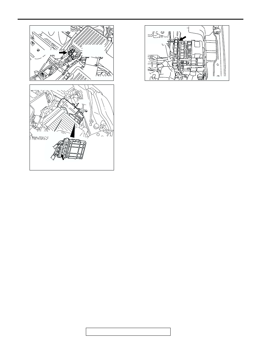
CONNECTOR: B-106

CAMSHAFT
POSITION
SENSOR

B-106 (B)

AK303043

CONNECTOR: B-22

B-22 (B)

PCM

AB

AIR CLEANER

AK303803AB

CONNECTOR: B-17X

MFI RELAY

B-17X

MULTIPORT FUEL INJECTION (MFI) DIAGNOSIS

TSB Revision

MULTIPORT FUEL INJECTION (MFI) <2.4L ENGINE>

13A-562

DTC SET CONDITIONS <Circuit continuity>

Logic Flow Chart

Check Conditions

• Engine speed is higher than 50 r/min.

Judgment Criteria

• Camshaft position sensor output voltage has not 

changed (no pulse signal is input) for 2 seconds.

.

START

MONITORING
CONDITIONS

END

NO

NO

NO

YES

YES

YES

MALFUNCTION

GOOD

OUTPUT SIGNAL

CHANGES

CONTINUOUS

FAILURE FOR 2secs

AK302034

MULTIPORT FUEL INJECTION (MFI) DIAGNOSIS

TSB Revision

MULTIPORT FUEL INJECTION (MFI) <2.4L ENGINE>

13A-563

DTC SET CONDITIONS <Range/Performance problem 

 alignment>

Logic Flow Chart

Check Conditions

• Engine speed is higher than 50 r/min.

Judgment Criteria

• Normal signal pattern has not been input for cyl-

inder identification from the crankshaft position 
sensor signal and camshaft position sensor sig-
nal for 2 seconds.

.

OBD-II DRIVE CYCLE PATTERN
Refer to Diagnostic Function 

− OBD-II Drive Cycle − 

Procedure 6 

 Other Monitor 

P.13A-5

.

.

TROUBLESHOOTING HINTS (The most likely 
causes for this code to be set are: )

• Camshaft position sensor failed.

• Open or shorted camshaft position sensor circuit, 

or harness damage, or connector damage.

• PCM failed.

DIAGNOSIS

Required Special Tool:

• MB991709: Test Harness

• MB991923: Power Plant ECU Check Harness

START

END

YES

NO

NO

YES

MALFUNCTION

GOOD

CONTINUOUS

FAILURE FOR

2secs

EXPECTED STATE

OF THE SENSOR

MONITORING 
CONDITIONS?

YES

NO

AK302035

MULTIPORT FUEL INJECTION (MFI) DIAGNOSIS

TSB Revision

MULTIPORT FUEL INJECTION (MFI) <2.4L ENGINE>

13A-564

STEP 1. Using the oscilloscope, check the camshaft 
position sensor.

(1) Disconnect the camshaft position sensor connector B-106, 

and connect test harness special tool (MB991709) between 
the separated connectors. (All terminals should be 
connected.)

(2) Connect the oscilloscope probe to the camshaft position 

sensor side connector terminal No. 2.
NOTE: When measuring with the PCM side connector, dis-
connect the all PCM connectors and connect check har-
ness special tool (MB991923) between the separated 
connectors. Then connect the oscilloscope probe to the 
check harness connector terminal No. 104.

(3) Start the engine and run at idle.

(4) Check the waveform.

• The waveform should show a pattern similar to the illus-

tration.

(5) Turn the ignition switch to the "LOCK" (OFF) position.
Q: Is the waveform normal?

YES : Go to Step 2.
NO :  Go to Step 4.

STEP 2. Check harness connector B-106 at camshaft 
position sensor for damage.

Q: Is the harness connector in good condition?

YES : Go to Step 3.
NO :  Repair or replace it. Refer to GROUP 00E, Harness 

Connector Inspection 

P.00E-2

. Then go to Step 20.

AK303863

1

2

3

AB

CONNECTOR: B-106

B-106 (B)

HARNESS CONNECTOR:
COMPONENT SIDE

AK102976AB

1 2 3

CAMSHAFT POSITION
SENSOR CONNECTOR

OSCILLOSCOPE

MB991709

AK301961AB

2 ENGINE REVOLUTIONS

NORMAL WAVEFORM

5V

AK303863

1

2

3

AB

CONNECTOR: B-106

B-106 (B)

HARNESS CONNECTOR:
COMPONENT SIDE


Content   ..  934  935  936  937   ..