Mitsubishi Galant (2004+). Manual - part 739
MANUAL A/C DIAGNOSIS
TSB Revision
HEATER, AIR CONDITIONING AND VENTILATION
55A-95
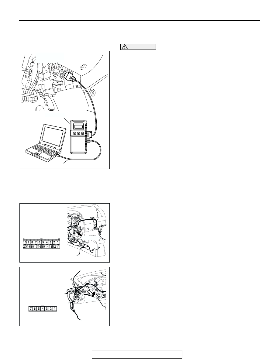
STEP 3. Using scan tool MB991958, check actuator test
item 13, 14, 15, 16, 17: Air outlet c/o dumper.
CAUTION
To prevent damage to scan tool MB991958, always turn the
ignition switch to the "LOCK" (OFF) position before con-
necting or disconnecting scan tool MB991958.
(1) Connect scan tool MB991958 to the data link connector.
(2) Start the engine.
(3) Use scan tool MB991958 to run the actuator test.
Item 13: air mix damper motor (FACE position)
Item 14: air mix damper motor (FOOT/FACE position)
Item 15: air mix damper motor (FOOT position)
Item 16: air mix damper motor (DEF/FOOT position)
Item 17: air mix damper motor (DEF position)
• Check that the mode selection damper control motor
operates.
(4) Turn the ignition switch to the "LOCK" (OFF) position.
Q: Is the sensor within the specified range?
YES : Replace the A/C-ECU. Then go to Step 7.
NO : Go to Step 4.
STEP 4. Check A/C-ECU connector C-15 and mode
selection damper control motor and potentiometer
connector C-102 for loose, corroded or damaged
terminals, or terminals pushed back in the connector.
Q: Are A/C-ECU connector C-15 and mode selection
damper control motor and potentiometer connector
C-102 in good condition?
YES : Go to Step 5.
NO : Repair or replace the connector. Refer to GROUP
00E, Harness Connector Inspection
to Step 7.
AC305412
AB
MB991910
DATA LINK
CONNECTOR
MB991824
MB991827
AC305233
CONNECTOR: C-15
BG
C-105 (B)
HARNESS SIDE
AC305231
C-102
HARNESS SIDE
CD
CONNECTOR: C-102