Mitsubishi Galant (2004+). Manual - part 397
DIAGNOSIS
TSB Revision
CONTROLLER AREA NETWORK (CAN)
54C-199
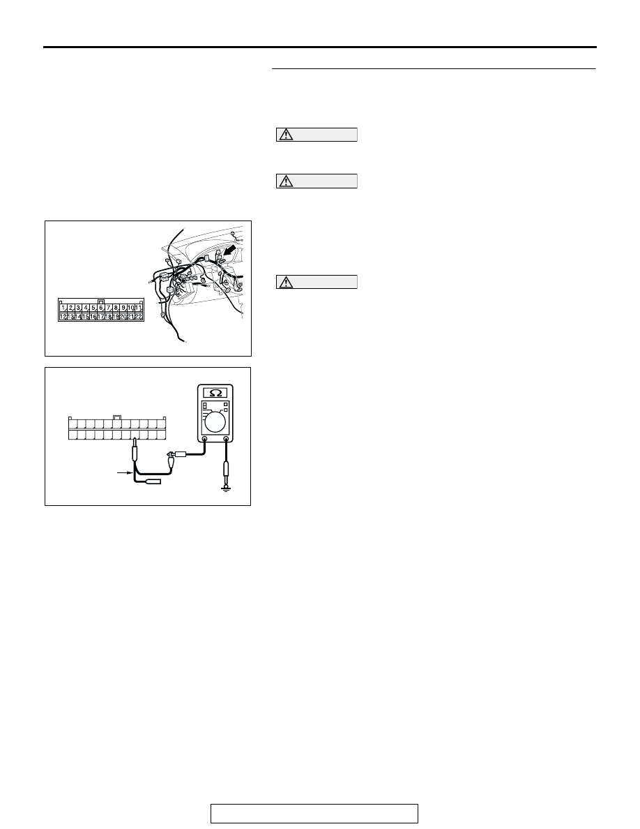
STEP 27. Check the CAN_L line (communication line
including the combination meter) between joint connector
(3) and the combination meter connector for short to
ground. Measure the resistance at joint connector (3) C-02.
CAUTION
A digital multimeter should be used. For details refer to
CAUTION
The test wiring harness should be used. For details refer to
(1) Disconnect joint connector (3) C-02, and measure the
resistance at the wiring harness side of joint connector (3)
C-02.
(2) Turn the ignition switch to the "LOCK" (OFF) position.
CAUTION
Disconnect the negative battery terminal. For details refer
to
.
(3) Disconnect the negative battery terminal.
(4) Measure the resistance between joint connector (3)
terminal 15 and body ground.
OK: 1 k
Ω or more
Q: Does the resistance measure 1 k
Ω or more?
YES : If the resistance measures 1 k
Ω or more, go to Step
29 .
NO : If the resistance measures less than 1 k
Ω, go to Step
28 .
AC305231AP
CONNECTOR: C-02
AC209364IG
11
22
10
21
9
20
8
19
7
18
6
17
5
16
4
15
3
14
2
13
1
12
HARNESS SIDE: C-02
TEST
HARNESS