Mitsubishi Galant (2004+). Manual - part 183
 

  Index      Mitsubishi     Mitsubishi Galant - service repair manual 2004 year


Search            


Content   ..  181  182  183  184   ..


Mitsubishi Galant (2004+). Manual - part 183


AUTO-CRUISE CONTROL

TSB Revision

ENGINE AND EMISSION CONTROL

17-23

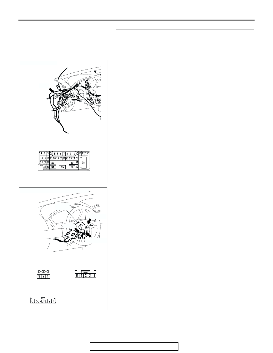
STEP 6. Check intermediate connector C-29, auto-cruise 
control switch connector C-302 and clock spring 
connectors C-303 and C-306 for loose, corroded or 
damaged terminals, or terminals pushed back in the 
connector.

Q: Are the connectors and terminals in good condition?

YES : Go to Step 7 .
NO :  Repair or replace the faulty connector (Refer to 

GROUP 00E, Harness Connector Inspection 

P.00E-2

), and install the air bag module (driver’s side) 

(Refer to GROUP 52B, Air Bag Modules and Clock 
Spring 

P.52B-368

). Then go to Step 18 .

AC305232

C-29

CONNECTOR: C-29

AC

C-29 MALE SIDE CONNECTOR

AC305236

C-306 HARNESS

CONNECTOR:

COMPONENT SIDE

C-303 HARNESS

CONNECTOR:

COMPONENT SIDE

C-302 HARNESS

CONNECTOR:

COMPONENT SIDE

AB

C-302 (Y)

C-303 (GR)

C-306

CONNECTORS: C-302, C-303, C-306

CLOCK

SPRING

AUTO-CRUISE CONTROL

TSB Revision

ENGINE AND EMISSION CONTROL

17-24

STEP 7. Check the harness wire between PCM connector 
B-19 terminal 12 and auto-cruise control switch connector 
C-302 terminal 2 for damage.

Q: Are the harness wires in good condition?

YES : Go to Step 8 .
NO :  Repair the damaged harness wire, and install the air 

bag module (driver’s side) (Refer to GROUP 52B, Air 
Bag Modules and Clock Spring 

P.52B-368

). Then go 

to Step 18 .

STEP 8. Check the clock spring.
Refer to GROUP 52B, Air Bag Modules and Clock Spring 

P.52B-374

.

Q: Is the clock spring in good condition?

YES : It can be assumed that this malfunction is intermittent 

(Refer to GROUP 00, How to Use 
Troubleshooting/Inspection Service Points 

− How to 

Cope with Intermittent Malfunction 

P.00-6

), and install 

the air bag module (driver’s side) (Refer to GROUP 
52B, Air Bag Modules and Clock Spring 

P.52B-368

). 

Then go to Step 18 .

NO :  Replace the clock spring and install the air bag 

module (driver’s side) (Refer to GROUP 52B, Air Bag 
Modules and Clock Spring 

P.52B-368

). Then go to 

Step 18 .

AC305710

B-19 HARNESS

CONNECTOR:

COMPONENT SIDE

AC

B-19 (B)

CONNECTOR: B-19

AIR CLEANER

PCM

AC305235AB

C-302 (Y)

CONNECTOR: C-302

C-302 HARNESS

CONNECTOR:

COMPONENT SIDE

CLOCK

SPRING

AUTO-CRUISE CONTROL

TSB Revision

ENGINE AND EMISSION CONTROL

17-25

STEP 9. Measure the ground voltage at auto-cruise control 
switch connector C-302 by backprobing.

(1) Do not disconnect auto-cruise control switch connector 

C-302.

(2) Turn the ignition switch to the "ON" position.
(3) Turn the "CRUISE" (MAIN) switch to the "ON" position.

(4) Measure the ground voltage between auto-cruise control 

switch connector C-302 terminal 3 and ground by 
backprobing.

(5) Turn the "CRUISE" (MAIN) switch to the "OFF" position.
(6) Turn the ignition switch to the "LOCK" (OFF) position.
Q: Is the measured voltage 0.5 volt or less?

YES : Go to Step 15 .
NO :  Go to Step 10 .

AC305235AB

C-302 (Y)

CONNECTOR: C-302

C-302 HARNESS

CONNECTOR:

COMPONENT SIDE

CLOCK

SPRING

1 2

AC209264

3

AB

C-302 HARNESS

CONNECTOR:

HARNESS SIDE

AUTO-CRUISE CONTROL

TSB Revision

ENGINE AND EMISSION CONTROL

17-26

STEP 10. Measure the ground voltage at PCM connector 
B-20.

(1) Disconnect all the connectors from the PCM.

(2) Connect special tool MB991923 between the PCM and the 

body-side harness connector.

(3) Turn the ignition switch to the "ON" position.
(4) Turn the "CRUISE" (MAIN) switch to the "ON" position.

AC305710

B-20 HARNESS

CONNECTOR:

COMPONENT SIDE

AD

B-20

CONNECTOR: B-20

AIR CLEANER

PCM

AC209793AL

SPECIAL TOOL 23-PIN CONNECTOR
WITHOUT RED TAPE
(PCM CONNECTOR B-20)

B-20

25

21

24 23 22

29 28 27 26

34 33 32 31 30

38 37 36 35

43 42 41 40 39

PCM

MB991923

BODY SIDE
HARNESS


Content   ..  181  182  183  184   ..