Mitsubishi Galant (2004+). Manual - part 1502


  Index      Mitsubishi     Mitsubishi Galant - service repair manual 2004 year


Search            


Content   ..  1500  1501  1502  1503   ..


Mitsubishi Galant (2004+). Manual - part 1502


MULTI-CENTER DISPLAY

TSB Revision

CHASSIS ELECTRICAL

54A-251

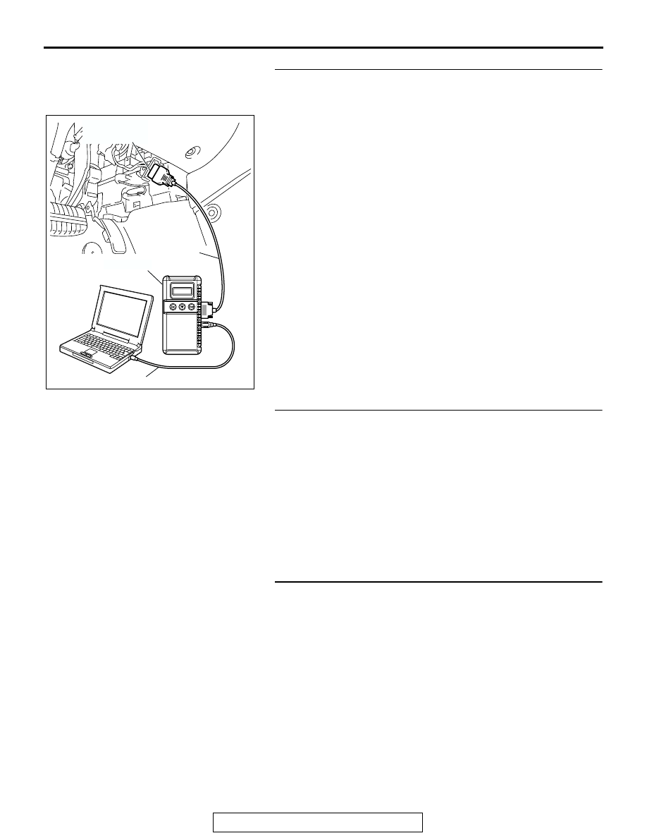
STEP 1. Using scan tool MB991958, diagnose the CAN bus 
line.
Use scan tool MB991958 to diagnose the CAN bus lines.
(1) Connect scan tool MB991958 to the data link connector.
(2) Turn the ignition switch to "ON" position.
(3) Diagnose the CAN bus line.
Q: Is the check result satisfactory?

YES : Go to Step 2.
NO :  Repair the CAN bus lines (Refer to GROUP 54C, 

Diagnosis-Can Bus Diagnostic Chart 

P.54C-14

). On 

completion, go Step 5.

STEP 2. Using scan tool MB991958, read the diagnostic 
trouble code related to the other system.
Check if a DTC, which relates to CAN communication-linked 
systems below, is set.
Powertrain control module

• DTC U1108: Combination meter time-out

ETACS-ECU

• DTC 014: Combination meter time-out

Q: Is the DTC set?

YES : Go to Step 3.
NO :  Go to Step 4.

STEP 3. Recheck for diagnostic trouble code.
Recheck if the DTC is set.

1. Erase the DTC.
2. Turn the ignition switch to "ON" position.
3. Check if the DTC is set.

Q: Is the check result satisfactory?

YES : A poor connection, open circuit or other intermittent 

malfunction is present in the CAN bus lines between 
the combination meter and the multi-center display 
unit (middle grade type) (Refer to GROUP 00, How to 
Use Troubleshooting/Inspection Service Points-How 
to Cope with Intermittent Malfunction 

P.00-6

).

NO :  Replace multi-center display unit (middle grade type) 

and then go to step 5.

AC305412

AB

MB991910

DATA LINK

CONNECTOR

MB991824

MB991827

MULTI-CENTER DISPLAY

TSB Revision

CHASSIS ELECTRICAL

54A-252

STEP 4. Recheck for diagnostic trouble code.
Recheck if the DTC is set.

1. Erase the DTC.
2. Turn the ignition switch to "ON" position.
3. Check if the DTC is set.

Q: Is the check result satisfactory?

YES : A poor connection, open circuit or other intermittent 

malfunction is present in the CAN bus lines between 
the combination meter and the multi-center display 
unit (middle grade type) (Refer to GROUP 00, How to 
Use Troubleshooting/Inspection Service Points-How 
to Cope with Intermittent Malfunction 

P.00-6

).

NO :  Replace multi-center display unit (middle grade type) 

and then go to step 5.

STEP 5. Recheck for diagnostic trouble code.
Recheck if the DTC is set.

1. Erase the DTC.
2. Turn the ignition switch to "ON" position.
3. Check if the DTC is set.

Q: Is the check result satisfactory?

YES : The procedure is complete.
NO :  Go to Step 1.

MULTI-CENTER DISPLAY

TSB Revision

CHASSIS ELECTRICAL

54A-253

DTC 019: ETACS-ECU Time-out

POWERTRAIN
CONTROL MODULE

JOINT
CONNECTOR (3)

WITHOUT ELECTRONIC 
BRAKE-FORCE 
DISTRIBUTION (EBD) 
AND ANTI-LOCK 
BRAKING 
SYSTEM (ABS)

WITH ELECTRONIC 
BRAKE-FORCE 
DISTRIBUTION (EBD) 
AND ANTI-LOCK 
BRAKING 
SYSTEM (ABS)

WITH ELECTRONIC 
BRAKE-FORCE 
DISTRIBUTION (EBD) 
AND ANTI-LOCK 
BRAKING 
SYSTEM (ABS)

WITHOUT ELECTRONIC 
BRAKE-FORCE 
DISTRIBUTION (EBD) 
AND ANTI-LOCK 
BRAKING 
SYSTEM (ABS)

ABS-ECU OR ABS/TCL-ECU

MULTI-CENTER 
DISPLAY UNIT

COMBINATION
METER

CPU

ETACS-ECU

Circuit of Time-out During CAN Communication with ETACS-ECU

MULTI-CENTER DISPLAY

TSB Revision

CHASSIS ELECTRICAL

54A-254

CAUTION

If DTC 019 is set in the ETACS-ECU, diagnose the 
CAN main bus line.

CAUTION

Whenever the ECU is replaced, ensure that the 
communication circuit is normal.

.

CIRCUIT OPERATION
The multi-center display unit (middle grade type) is 
linked to CAN communication lines to communicate 
with the combination meter and the powertrain con-
trol module, both of which have a terminator resistor.

.

DTC SET CONDITION
The multi-center display unit (middle grade type) 
communicates with the ETACS-ECU via CAN bus 
lines. If it can not receive all the necessary signals 
from the ETACS-ECU, DTC 019 is set.

.

TECHNICAL DESCRIPTION (COMMENT)

Current trouble

• Connector(s) or wiring harness in the CAN bus 

lines between the ETACS-ECU and the 
multi-center display unit (middle grade type), the 
power supply system to the display unit, the dis-
play unit itself, or the ETACS-ECU may be defec-
tive.

AC305206

CONNECTOR: A-02

AO

A-02 (GR)

AC305216

B-19 (B)

CONNECTOR: B-19

AD

AC305233

C-05 (B)

CP

CONNECTOR: C-05

AC305231

C-02

C-29

C-101

DD

CONNECTORS: C-02, C-29, C-101

AC305413AL

CONNECTOR: C-218

C-218 (GR)


Content   ..  1500  1501  1502  1503   ..